

Organic fuel cell
A fuel cell and battery technology, applied in the direction of fuel cells, fuel cell additives, fuel cell components, etc., can solve the problem of low power density and achieve the effect of increasing power density and speed
- Summary
- Abstract
- Description
- Claims
- Application Information
AI Technical Summary
Problems solved by technology
Method used
Image

Examples
Embodiment 1
[0051] This example illustrates a fuel cell provided by the present invention.
[0052] A battery as shown in FIG. 8 was prepared, and the heat conducting member 3 was located between the battery case 4 and the cathode deflector 23 .
[0053] Wherein, the heat conduction component 3 is an aluminum plate with a size of 100 mm×100 mm×1 mm, and through holes penetrating through the thickness direction are distributed on the aluminum plate, and the area of the through holes is 375 square millimeters. The catalyst is a carbon-supported platinum-ruthenium catalyst of J-M Company, wherein the weight percentage of platinum is 20% by weight, the weight percentage of ruthenium is 10% by weight, and the platinum-ruthenium loading is 4 mg / cm 2 , the size of the anode 11 is 50 mm × 50 mm × 0.3 mm, the anode deflector 21 and the cathode deflector 23 are graphite, and the size is 50 mm × 50 mm × 0.3 mm.
[0054] The supporting material of the negative electrode 13 is carbon fiber, and the...
Embodiment 2
[0057] This example illustrates a fuel cell provided by the present invention.
[0058] A battery as shown in FIG. 9 was prepared, and there were two heat conducting members 3 , which were respectively located between the battery case 4 and the cathode deflector 23 and between the battery case 4 and the anode deflector 21 .
[0059] Among them, the heat-conducting parts 3 are all copper plates with a size of 150 mm × 150 mm × 0.5 mm. The copper plate is distributed with through holes through the thickness direction. The area of the through holes is 375 square millimeters. The supporting material of the anode 11 is carbon fiber. 11 The catalyst is a carbon-supported platinum-ruthenium catalyst of J-M Company, wherein the weight percentage of platinum is 20% by weight, the weight percentage of ruthenium is 10% by weight, and the platinum-ruthenium loading is 4 mg / cm 2 , the size of the anode 11 is 60 mm × 60 mm × 0.3 mm, the anode deflector 21 and the cathode deflector 23 are ...
Embodiment 3
[0064] This example illustrates a fuel cell provided by the present invention.
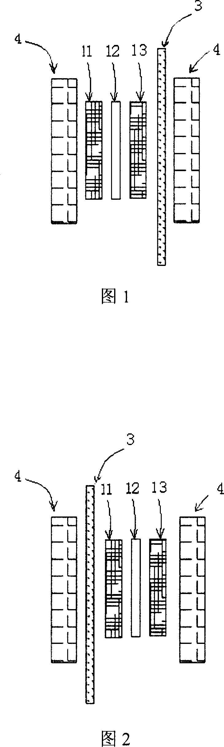
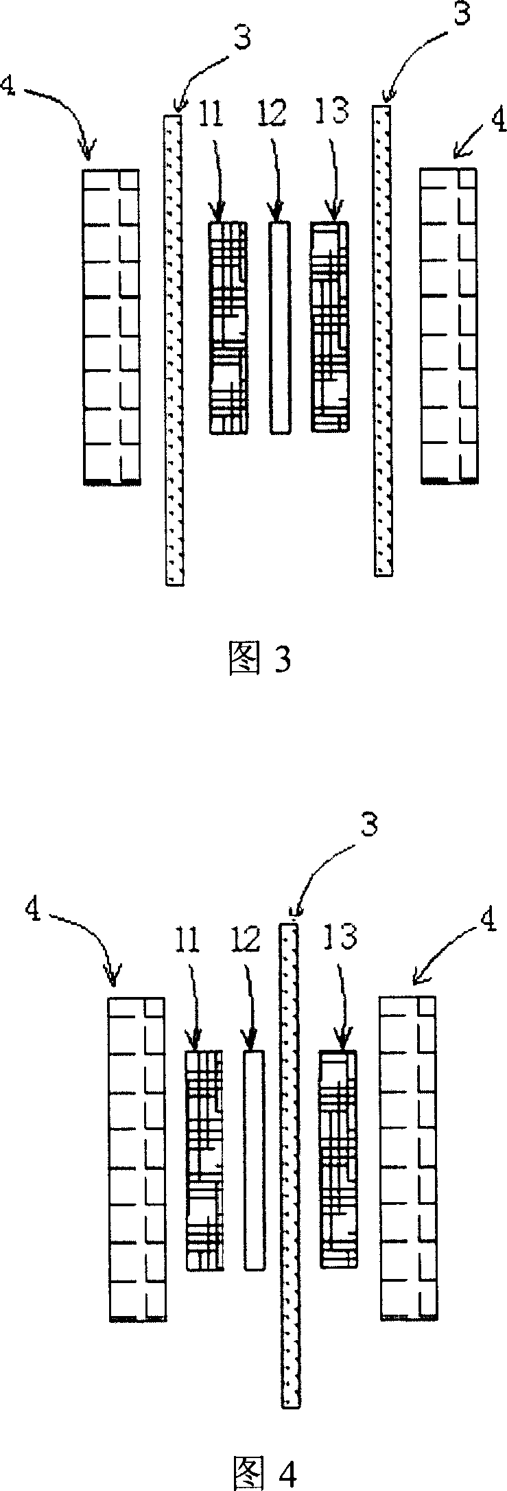
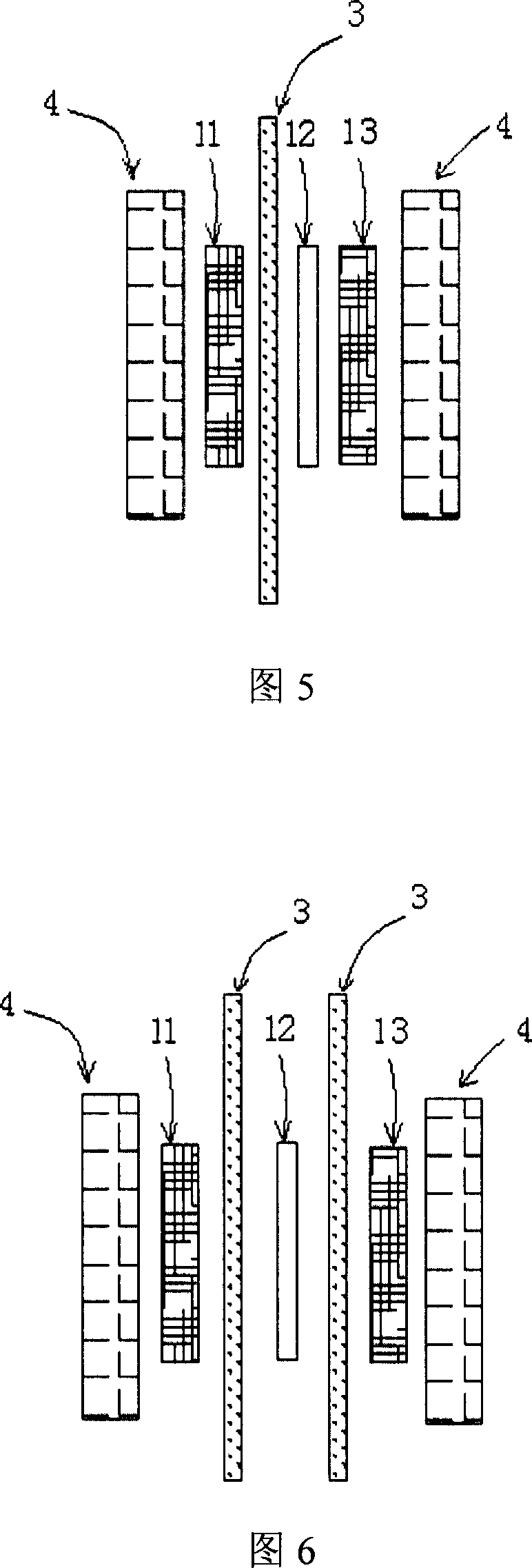
[0065] A battery as shown in FIG. 5 was prepared, and the heat conducting member 3 was located between the anode 11 and the proton exchange membrane 12 .
[0066]Among them, the heat-conducting component 3 is a gold-plated copper sheet with a size of 45mm×45mm×0.2mm after hydrophilic treatment. There are through holes running through the thickness direction on the gold-plated copper sheet. The area of the through hole is 375 square millimeters. The hydrophilic treatment process In order to immerse the above-mentioned heat-conducting parts in 5% Nanfion solution for 10 minutes, then blow dry at room temperature, and then dry at 120°C for 30 minutes under the protection of an inert gas; the support material of the anode 11 is carbon fiber, and the catalyst of the anode 11 is the carbon of J-M Company Loaded platinum-ruthenium catalyst, wherein the weight percentage of platinum is 20% by weight, th...
PUM
| Property | Measurement | Unit |
|---|---|---|
| Thickness | aaaaa | aaaaa |
Abstract
Description
Claims
Application Information