Heat exchanger employing crossed spiral tube

A heat exchanger and heat exchange tube technology, applied in the direction of heat exchanger types, indirect heat exchangers, heat exchange equipment, etc., can solve the problems of high manufacturing cost and complex structure, and achieve compact structure, small volume, and processing capacity. big effect

Active Publication Date: 2008-01-09
辽宁联友博科技有限公司
View PDF0 Cites 5 Cited by
  • Summary
  • Abstract
  • Description
  • Claims
  • Application Information

AI Technical Summary

Problems solved by technology

This type of heat exchanger has compact structure and high heat exchange efficiency, but the structure is complex and the manufacturing cost is high

Method used


Image

  • Heat exchanger employing crossed spiral tube
  • Heat exchanger employing crossed spiral tube
  • Heat exchanger employing crossed spiral tube

Examples


Embodiment 1

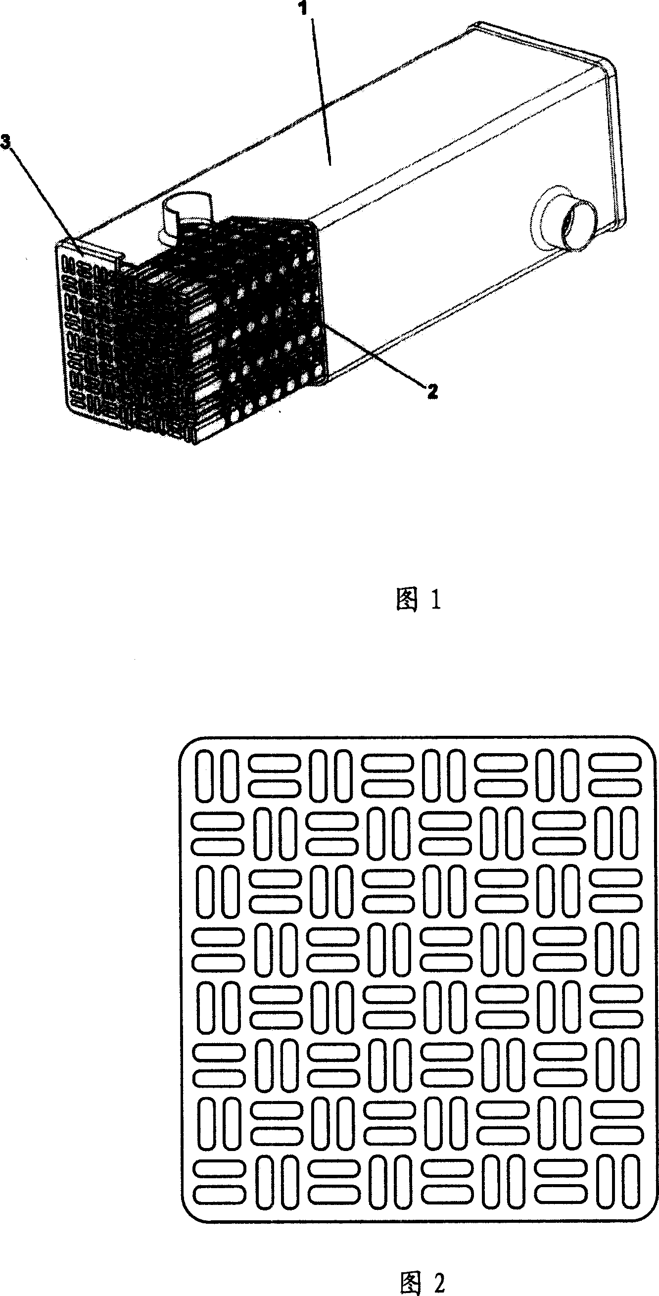
[0023] Figures 1 and 2 are respectively a three-dimensional structural schematic diagram and a cross-sectional shape schematic diagram at the tube sheet of the first embodiment of the present invention. The serial numbers in the figure represent: 1. Shell, 2. Heat exchange tube, 3. Tube sheet. As shown in Figure 1, when the shell 1 of the heat exchanger has a rectangular cross-section, a flat cross-helical groove heat exchange tube 2 is arranged in the shell 1; the heat exchange tube 2 is compactly arranged in the shell 1 , and the heat exchange tubes 2 are staggeredly arranged in the shell in parallel and vertical ways, and the two ends of the nozzles of the heat exchange tubes 2 are welded and fixed on the tube plates 3 at both ends of the shell. The application of flat intersecting spiral tubes and the arrangement shown in Figure 1 not only enhance the flow strength of the fluid in the tube, but also enhance the disturbance of the fluid of the coolant outside the tube, maki...

Embodiment 2

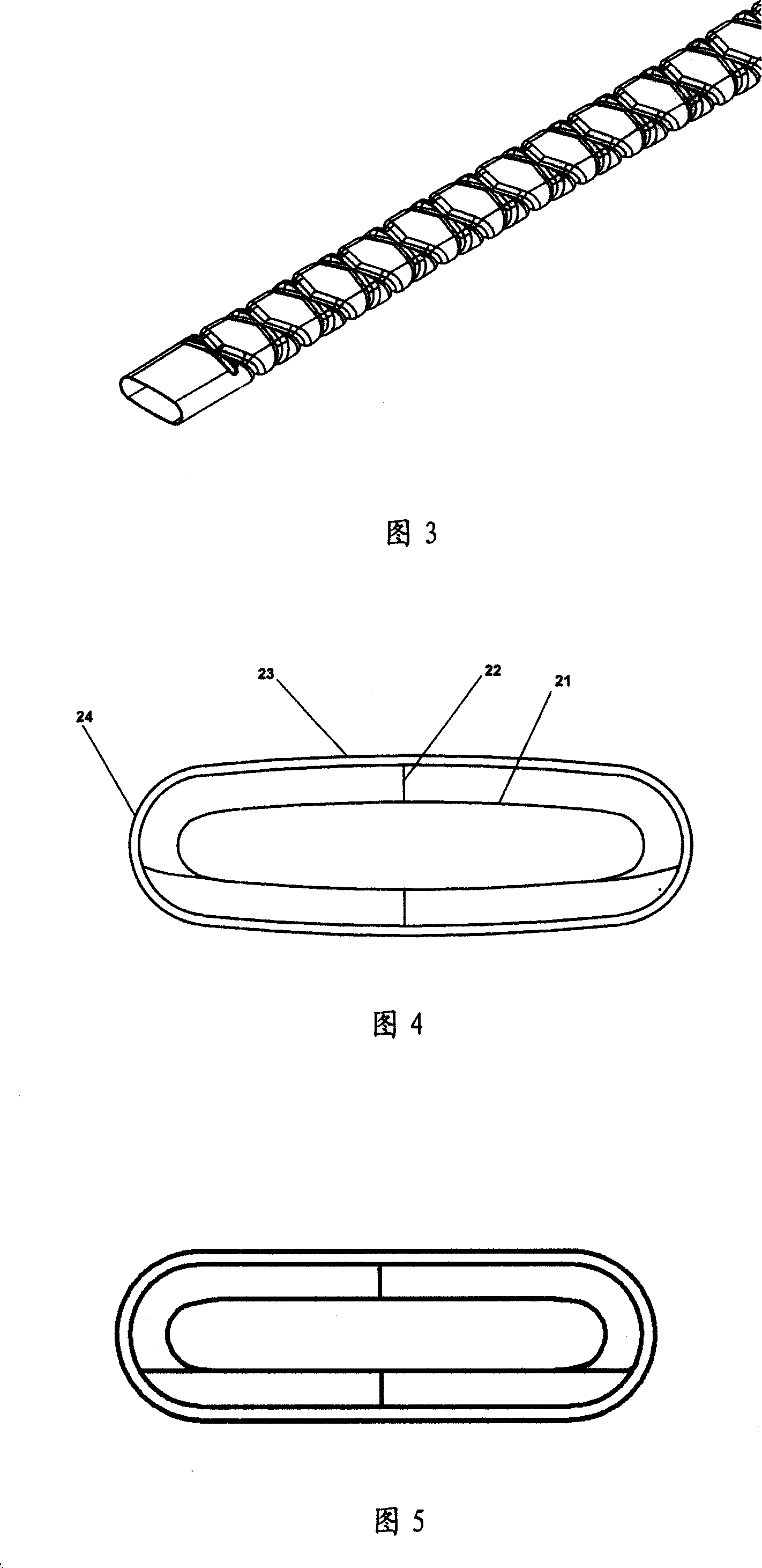
[0032] The cross-sectional shape of the heat exchange tube in this embodiment is another oblate shape, as shown in FIG. 5 . The difference between this embodiment and the first embodiment described in Figure 4 above is that the cross-sectional shape of the stainless steel pipe body is flat, the two opposite long sides are straight lines, and the opposite short sides are arc-shaped raised semicircular arcs from the inside to the outside. On the other hand, such a setting can improve the heat exchange efficiency.

[0033] The flat spiral heat exchange tube arranged in the exhaust gas recirculation cooler not only increases the heat exchange area compared with the circular tube, but also strengthens the disturbance of the fluid in the tube. Because the flat tube is not symmetrical to the center of the round tube, the distance between the geometric center of the flat spiral tube and the tube wall is smaller than the distance between the circular spiral tube and the tube wall, and ...

Embodiment 3

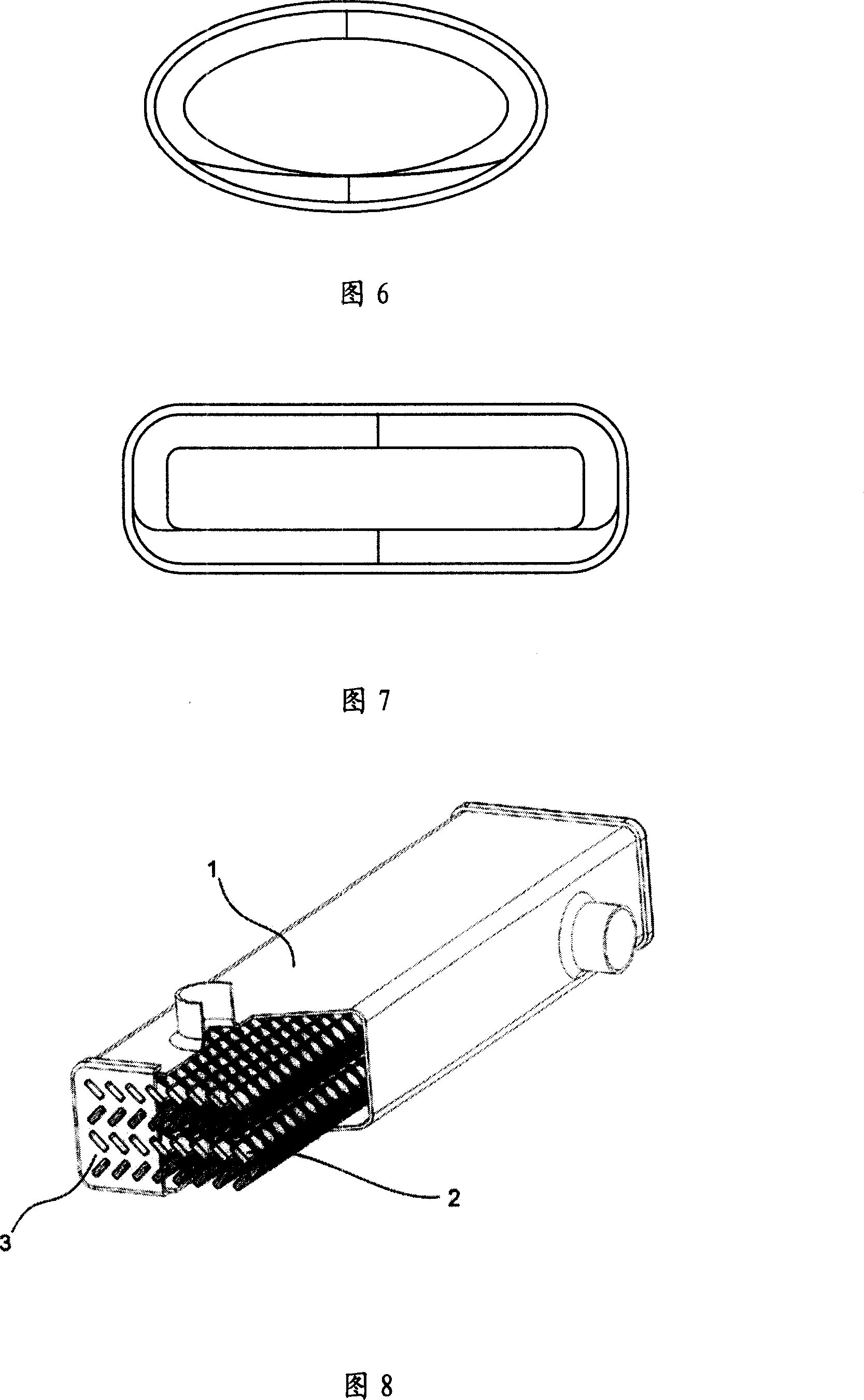
[0035] Fig. 6 is a sectional view of the heat exchange tube in this embodiment. This embodiment is a modification based on the embodiment described in Figure 4 above, connecting the entire cross-section of the heat exchange tubes smoothly, that is, for the sake of processing, in the case of removing the cross-sectional shape of the spiral groove, the The cross-sectional shape of the pipe body is set as an ellipse.


PUM


Abstract

The invention relates to a heat exchanger which used the cross-helical tube, involving an exhaust recycle heat exchanger. For improving the engine exhaust recycle heat exchanger and increasing the heat exchange efficiency. The exchanger includes the heat exchange tube, shell and the tube board. Of which the heat exchange tube is the stainless steel tube which has the entad raised cross-helical groove on the surface, and the section shape of the tube is the flat shape. The height and width of the section shape in the flat shape heat exchange tube are unlikeness, and the opposite rotating direction helix line cross on the relative long edge of the tube as the 'X' shape. Because of the application of the cross-helical heat exchange tube, the tube inside and outside is not easy to dirty and increased the heat exchange efficiency, the heat exchanger is particularly suitable for the exhaust gas recycle coolers of a vehicle engine, reduce the exhaust discharge temperature and enhance the vehicle engine discharge performance indicators to meet environmental discharge requirement. At the same time, the invention can also be used in a turbocharger system to improve the engine performance.

Description

technical field [0001] The invention relates to a heat exchanger using crossed spiral tubes, relates to an exhaust gas recirculation heat exchanger of an engine, is an additional device for intake and exhaust of an engine, and is a cross channel between a heat exchange tube and a heat exchange medium. Hand heat exchanger. Background technique [0002] Heat exchangers are widely used in petrochemical, machinery manufacturing, oil refining, metallurgy, light industry, pharmaceutical, food and other industries, accounting for 40% to 60% of all process equipment investment, so the development of heat exchangers has a great impact on these industries Impact. Due to the continuous increase of energy and material costs, the development of high-efficiency energy-saving heat exchangers has been greatly promoted. In the automobile manufacturing industry, as countries all over the world have stricter requirements on automobile exhaust emission standards, the optimal design of heat ex...

Claims


Application Information

Patent Timeline
Patent Type & Authority Applications(China)
IPC IPC(8): F28F1/06F28F1/42F28D1/04
Inventor 景建周景建坤杨晓瑷沈董浩汤俊洁
Owner 辽宁联友博科技有限公司
Why Eureka
Try Eureka