Single-level power factor correction converter circuit

A power factor correction and converter technology, which is applied in the direction of output power conversion device, conversion equipment with intermediate conversion to AC, electrical components, etc., can solve the problem of high voltage stress of switching devices, high surge voltage of power supply, main circuit Complicated problems, to achieve the effect of improving power factor, improving power supply efficiency, and reducing electromagnetic interference

Inactive Publication Date: 2008-01-09
曹文领
View PDF1 Cites 9 Cited by
  • Summary
  • Abstract
  • Description
  • Claims
  • Application Information

AI Technical Summary

Problems solved by technology

The disadvantage of the previous article is that the surge current is large when the power is turned on, the main circuit is complex, the cost is high, the energy storage capacitor, the switching device voltage stress is high, and the power consumption is large; the disadvantage of the latter article is that the main circuit is complicated, the cost is high, and the output 100Hz ripple High voltage, high surge voltage when the power is turned on

Method used


Image

  • Single-level power factor correction converter circuit

Examples


Embodiment Construction

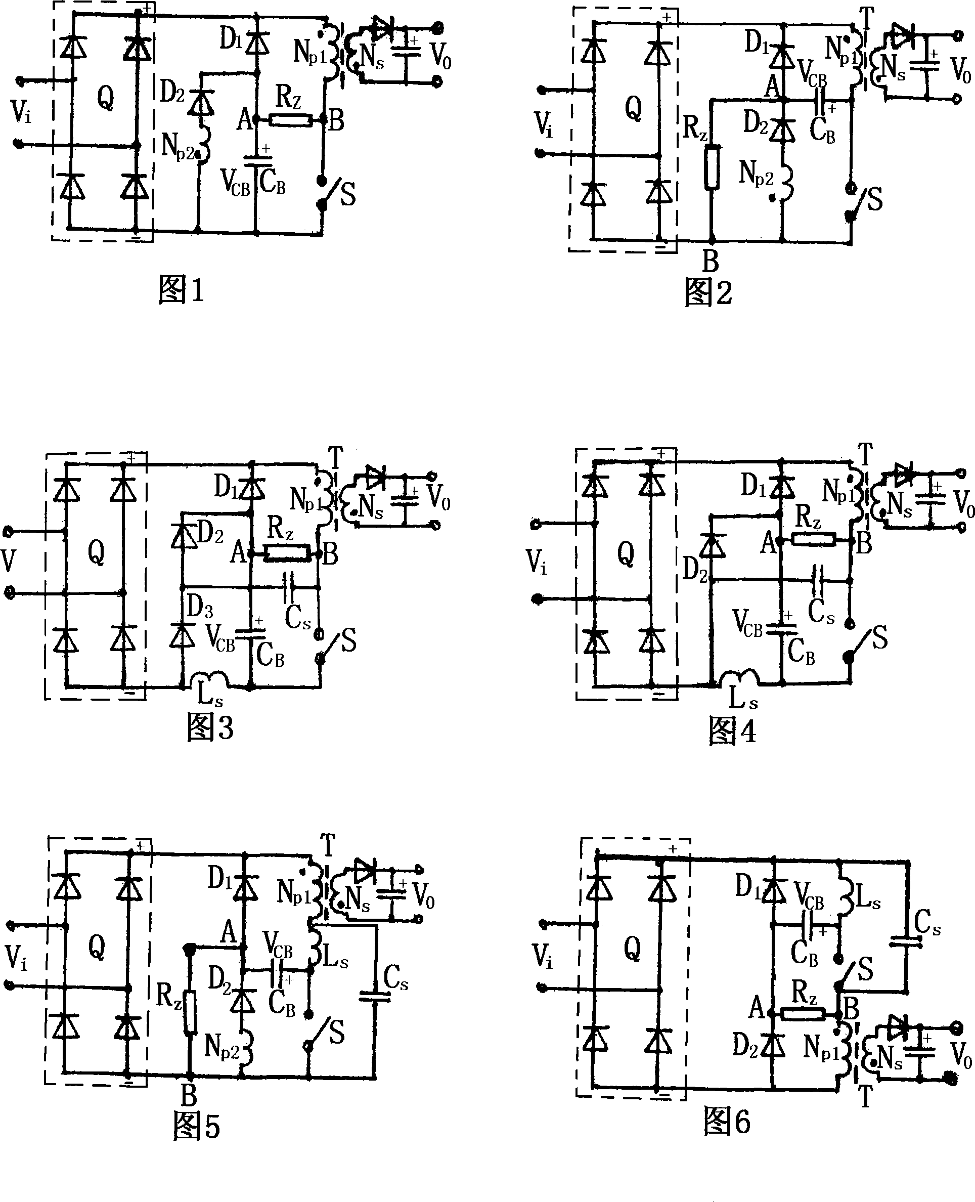
[0018] In Figure 1, the mains V i The two ends of the rectifier bridge Q are tapped to the two AC input terminals, the positive output terminal of the rectifier bridge Q, and the primary winding N of the transformer T p1 Upper end, first diode D 1 Negative junction; first diode D 1 Positive electrode, energy storage capacitor C B Anode of the second diode D 2 (Positive down) with transformer T second winding N p2 The upper end of the series circuit is connected, the transformer T primary winding N p1 The lower end and the upper end of the switch S are connected; the lower end of the switch S is connected to the energy storage capacitor C B Negative pole, second diode D 2 with the second winding N of the transformer T p2 The lower end of the series circuit and the negative output end of the rectifier bridge Q are connected together. The secondary winding N of the switching transformer T s Connected with an output rectification filter circuit, when AC output is required...


PUM


Abstract

The invention is concerned with the correcting convertor of the single power factor circuit. The positive output end of the rectifier of the transformer meets the tip of the primary winding of the transformer, the bottom of the primary winding of the transformer meets the negative output end of the rectifier with the switch in the middle, the cathode of the first diode meets the positive end of the rectifier, the anode of the first diode meets the negative end of the rectifier with the circuit in series in the middle, which composes by the second diode and the second winding of the transformer, the storing capacitance anode meets the connecting point that is in the middle of the series circuit and the first diode anode, the storing capacitance cathode meets the negative end of the rectifier. The invention can eliminate the surge current generated by the power during starting up, can reduce the voltage of the storing capacitance to less than 250V, and it can recycle the magnet leakage energy of the transformer to improves power efficiency. It suits for the switch power in middle or small power.

Description

technical field [0001] The invention relates to a single-stage power factor correction converter circuit and belongs to the technical field of switching power supplies. Background technique [0002] For known single-stage power factor correction converters, see the article "A Review of the Improved Single-Stage Power Factor Correction AC / DC Converter Topology" published in the "Power Supply Technology Application" magazine in February 2004 and "One A single-stage power factor correction circuit" invention patent specification, the publication number is CN1545192A. Their advantage is that the control circuit is simple and the cost is slightly lower. The disadvantage of the previous article is that the surge current is large when the power is turned on, the main circuit is complex, the cost is high, the energy storage capacitor, the switching device voltage stress is high, and the power consumption is large; the disadvantage of the latter article is that the main circuit is c...

Claims


Application Information

Patent Timeline
Patent Type & Authority Applications(China)
IPC IPC(8): H02M1/42H02M3/28
CPCY02B70/126Y02B70/10
Inventor 曹文领
Owner 曹文领
Why Eureka
Try Eureka