A harmonic vibration converter

A resonant converter and transformer technology, which is applied in the direction of converting AC power input to DC power output, output power conversion devices, electrical components, etc., can solve the problems of large capacitance and inductance parameters of the output filter circuit, increase, and decrease in efficiency. , to achieve the effect of optimal design

Active Publication Date: 2008-01-16
ASTEC POWER SUPPLY (SHENZHEN) CO LTD
View PDF0 Cites 48 Cited by
  • Summary
  • Abstract
  • Description
  • Claims
  • Application Information

AI Technical Summary

Problems solved by technology

[0005] To sum up, the existing resonant converters have the following disadvantages: when the load is light or no-load, in order to reduce the output voltage, it is necessary to increase the switching frequency. Since the characteristic curve becomes very flat when the frequency increases to a certain value, it is necessary to reduce the voltage. Increase the switching frequency very high, resulting in a wide operating frequency range of the converter
The wide range of switching frequency of the converter makes it difficult to optimize the output filter circuit, and the output filter circuit must meet the requirements of the lowe

Method used


Image

  • A harmonic vibration converter
  • A harmonic vibration converter
  • A harmonic vibration converter

Examples


specific Embodiment approach 1

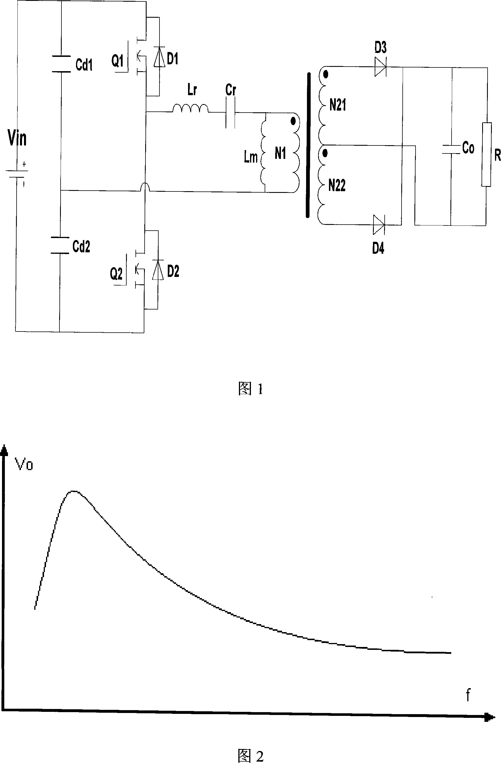
[0030] The present invention improves the existing control method of the LLC resonant converter with symmetrical half-bridge structure as shown in Fig. The AC square wave voltage of the empty ratio is output to the resonant circuit, and the fixed frequency satisfies the following formula:

[0031] f m r , fr = 1 2 π LrCr , f m = 1 2 π ( L r + L m ) C r

[0032]Wherein f is the fixed frequency, fr is the first characteristic resonant frequency of th...

specific Embodiment approach 2

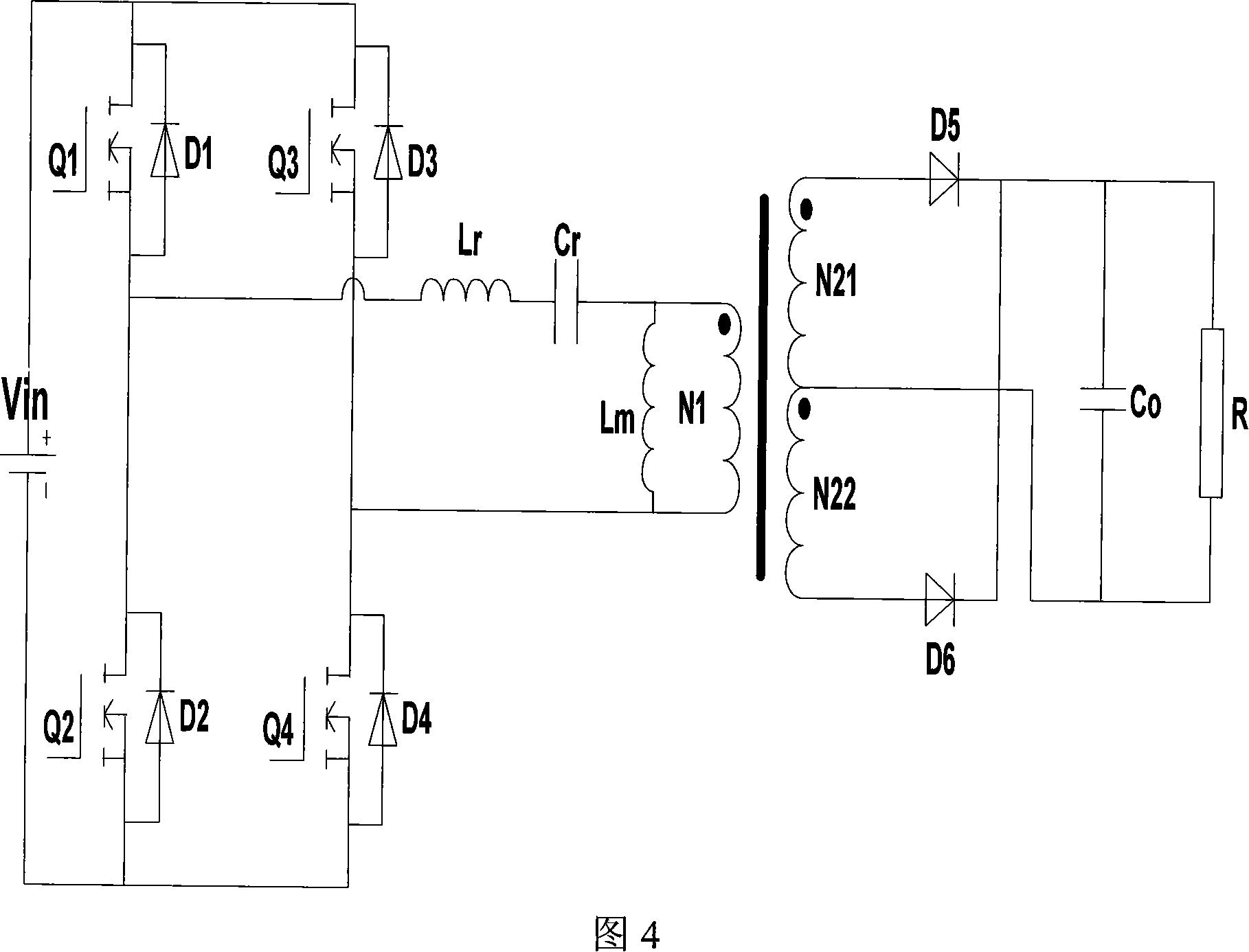
[0050] As shown in Figure 4, the present invention can also improve the control method of the full-bridge LLC resonant converter, the difference between the full-bridge LLC resonant converter and the half-bridge LLC resonant converter shown in Figure 1 is that: The square wave generator includes a first switching tube Q1, a second switching tube Q2, a third switching tube Q3, and a fourth switching tube Q4, and the first switching tube Q1 and the second switching tube Q2 are connected in series to the DC power supply At both ends, the third switching tube Q3 and the fourth switching tube Q4 are connected in series across the two ends of the DC power supply; one end of the first inductor Lr is connected between the first switching tube Q1 and the second switching tube Q2, The other end of the first inductance Lr is connected to one end of the second inductance Lm and the primary winding N1 of the transformer through the resonant capacitor Cr, and the other end of the second indu...

specific Embodiment approach 3

[0052] Fig. 5 is a schematic structural diagram of an interleaved parallel symmetrical half-bridge LLC resonant converter controlled by PWM in this specific embodiment. The difference between this specific embodiment and specific embodiment 1 is that two symmetrical half-bridge LLC resonant converters are used to interleave in parallel.

[0053] The resonant converter shown in Figure 5 includes first and second transformers, first and second square wave generators, first and second resonant circuits, first and second output rectifier circuits; the first output rectifier circuit is connected to Between the secondary windings N21 and N22 of a transformer and the output filter circuit, the input terminal of the first square wave generator is connected with a DC power supply Vin, and the first square wave generator is used to convert the input DC voltage into an AC square wave The first resonant circuit includes a first inductance Lr1, a first resonant capacitor Cr1, and a second ...


PUM


Abstract

The invention discloses a resonant converter comprising a transformer, a square wave generator, a resonant circuit, an output rectifying circuit, and an output filtering circuit, wherein the output rectifying circuit is connected between the secondary line winding of the transformer and the output filtering circuit; the input terminal of the square wave generator is connected with DC power supply; the square wave generator is used to convert the input DC voltage into square wave AC voltage and export; the resonant circuit comprises a first inductor, a resonant capacitor, and a second inductor; the resonant capacitor and the first inductor are series-connected into a resonant branch; the second inductor and the first line winding of the transformer are parallel-connected into a parallel branch; one end of the resonant branch is connected with one end of the parallel branch; the other ends of the resonant branch and the parallel branch are respectively connected with the two output terminals of the square wave generator. The square wave AC voltage from the square wave generator has fixed frequency and adjustable duty ratio, which can prevent working frequency of the converter from being in a wide range, optimizing the design of the output filtering circuit.

Description

technical field [0001] The invention relates to a resonant converter. Background technique [0002] As shown in Figure 1, a symmetrical half-bridge structure LLC resonant converter includes a transformer, a square wave generator, a resonant circuit, an output rectifier circuit and an output filter circuit, and the output rectifier circuit is connected to the secondary winding of the transformer and the output filter circuit Between the circuits, the input terminal of the square wave generator is connected with a DC power supply, and the square wave generator is used to convert the input DC voltage Vin into an AC square wave voltage and output it. The transformer includes a primary winding N1, a first secondary winding N21, and a second secondary winding N22. The square wave generator includes a first capacitor Cd1, a second capacitor Cd2, a first switching tube Q1 and a second switching tube Q2. The capacity of the first capacitor Cd1 and the second capacitor Cd2 is large,...

Claims


Application Information

Patent Timeline
IPC IPC(8): H02M7/523H02M1/12
Inventor 李小兵
Owner ASTEC POWER SUPPLY (SHENZHEN) CO LTD
Why Eureka
Try Eureka