
Liquid crystal display device, optical compensatory sheet, and polarizer and liquid crystal display device employing the same

A liquid crystal display device, optical compensation film technology, applied in optics, polarizing elements, nonlinear optics, etc., can solve problems such as unsatisfactory performance, no consideration of differences, and inability to completely suppress light leakage.

Active Publication Date: 2008-01-16
FUJIFILM CORP
View PDF52 Cites 17 Cited by
  • Summary
  • Abstract
  • Description
  • Claims
  • Application Information

AI Technical Summary

Problems solved by technology

However, even these methods require bonding a plurality of films, and thus are not satisfactory from the viewpoints of thickness reduction and production cost reduction
Furthermore, there are problems in that light leakage in the oblique direction of the polarizer in the dark state cannot be completely suppressed in the visible light region, and the expansion of the viewing angle is insufficient
More importantly, it is difficult to completely compensate light leakage for the entire wavelength range of visible light at the incident angle with respect to the oblique direction of the polarizer in the dark state, and thus there is a problem that azimuthal direction dependence of chromatic aberration occurs
A method of preventing light leakage by controlling the dispersion of the retardation film has also been proposed (see JP-A 2002-221622), but there is a problem that the difference between the dispersion of the in-plane retardation and the dispersion of the thickness direction retardation is not considered, and suppressing Lack of light leaks
Therefore, the performance is unsatisfactory from the viewpoint of improving chromatic aberration in the case of a viewing angle tilted from the front in a dark state

Method used


Image

  • Liquid crystal display device, optical compensatory sheet, and polarizer and liquid crystal display device employing the same
  • Liquid crystal display device, optical compensatory sheet, and polarizer and liquid crystal display device employing the same
  • Liquid crystal display device, optical compensatory sheet, and polarizer and liquid crystal display device employing the same

Examples


no. 1 approach

[0144] A first embodiment of the present invention is described below.

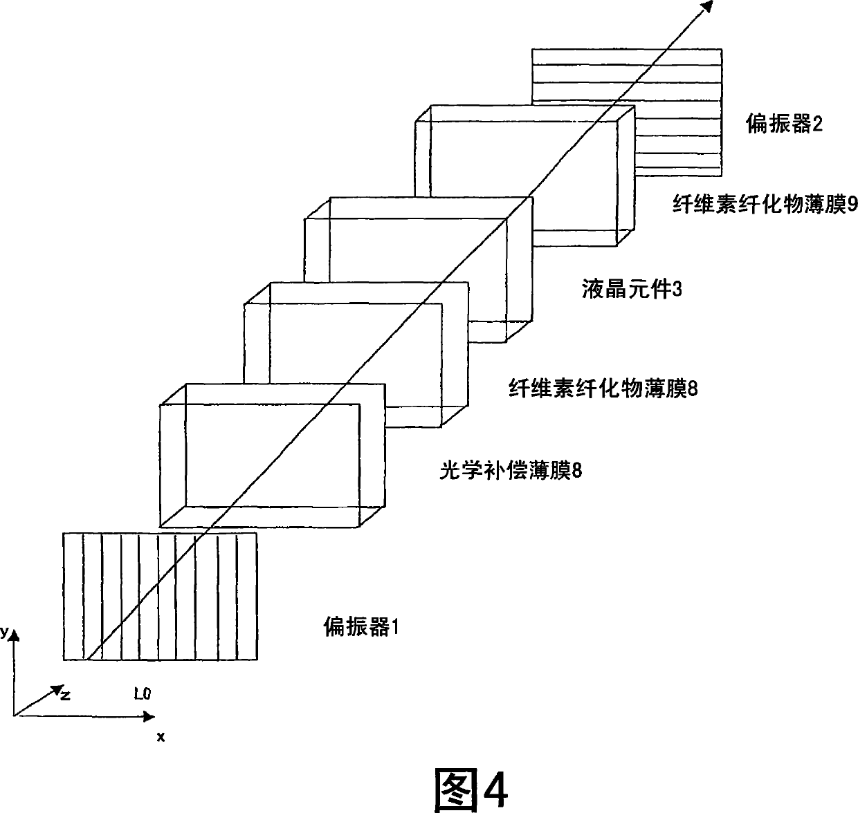
[0145] The liquid crystal display device of the first embodiment includes: a liquid crystal panel in which a liquid crystal with negative dielectric anisotropy is interposed between an upper substrate and a lower substrate, the liquid crystal has been vertically aligned on the surface, so that The orientation of the liquid crystal is almost vertical when no voltage is applied, almost horizontal when a predetermined voltage is applied, and tilted when a voltage smaller than the predetermined voltage is applied; the first polarizer and the second polarizer placed on both sides of the liquid crystal panel a polarizer, wherein absorption axes of the polarizers are perpendicular to each other; a first retardation film placed between the liquid crystal panel and the first polarizer; and a first retardation film placed between the liquid crystal panel and the second polarizer and a second retardation film betwee...

Embodiment approach

[0542] According to the first embodiment, the manufacturing method of the polarizer is not particularly limited, and a conventional manufacturing method can be used. There may be mentioned a method of subjecting the obtained cellulose acylate film to an alkali treatment, and adhering the treated cellulose acylate film to both sides of a polarizer with an aqueous solution of a completely saponified polyvinyl alcohol solution, which Polarizers are made by dipping and stretching a polyvinyl alcohol film in an iodine solution. Cellulose acylate films may be subjected to good adhesion processing as described in JP-A 6-94915 and 6-118232 instead of alkali treatment.

[0543] Adhesives for bonding the treated surface of the protective film and the polarizing film can be exemplified by polyvinyl alcohol-based adhesives such as polyvinyl alcohol or polyvinyl butyral, or vinyl latex such as butyl acrylate, and the like.

[0544] The polarizer is composed of a polarizing film and a prot...

no. 2 approach

[0575] Next, a second embodiment of the present invention is described.

[0576] Next, the operation of the second embodiment will be described with reference to the drawings.

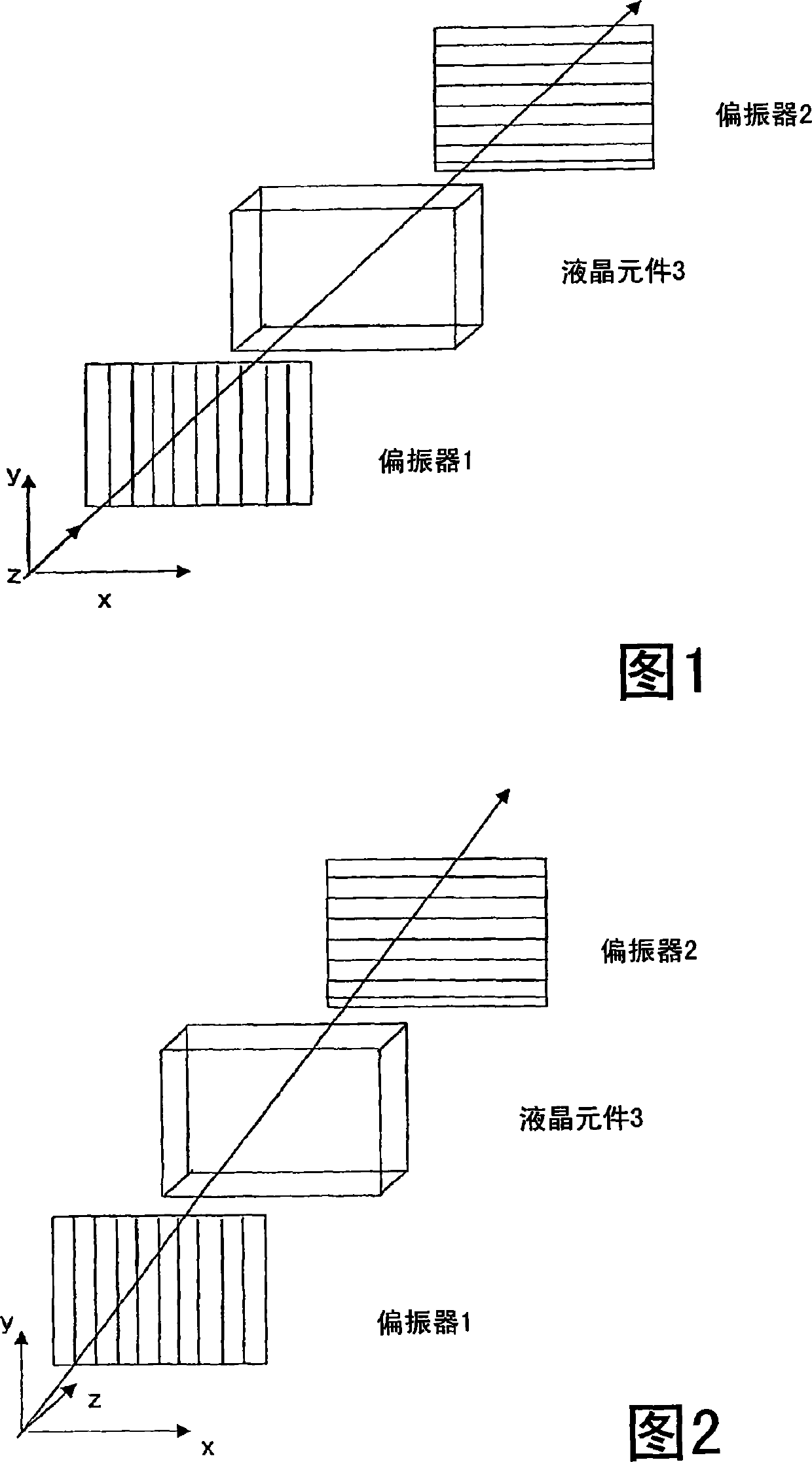
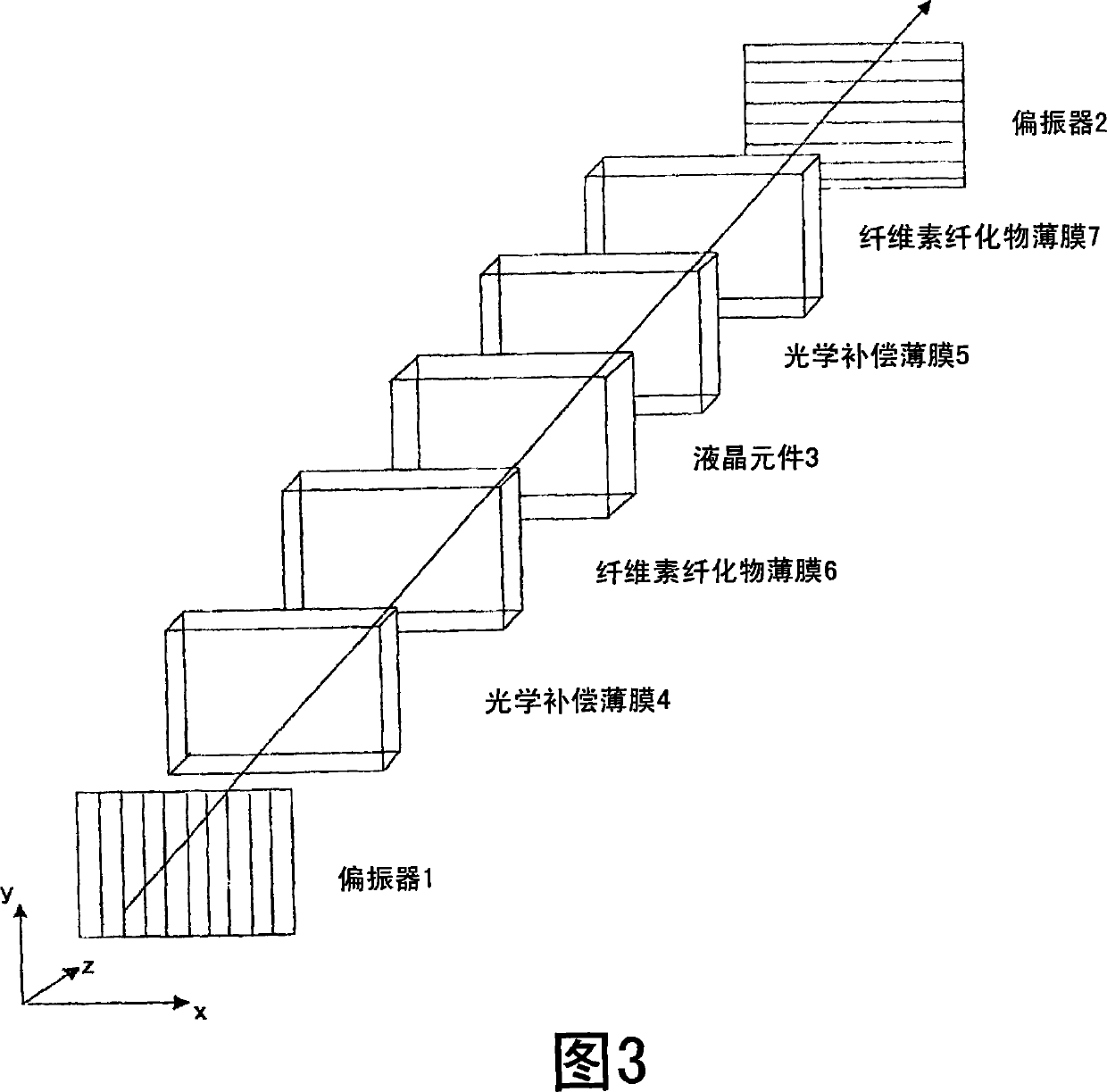
[0577] FIG. 1 is a schematic diagram describing the structure of a conventional VA type liquid crystal display device. The VA type liquid crystal display device has a liquid crystal element 3 with a liquid crystal layer in which the liquid crystal is vertically aligned with respect to the substrate surface when no voltage is applied, that is, during a black state; and the polarizer 1 and the polarizer in which the liquid crystal element 3 is inserted. 2, and installed so that their transmission axes (shown by the arrows in Figure 1) are placed perpendicular to each other. In FIG. 1 , light is incident from the polarizer 1 side. When no voltage is applied, when light traveling along the normal direction, that is, the z-axis direction is incident, the light passing through the polarizer 1 maintains a l...


PUM

PropertyMeasurementUnit
Thicknessaaaaaaaaaa

Abstract

A liquid crystal display device comprising a liquid crystal panel in which liquid crystals having negative dielectric anisotropy are interposed between upper substrate and lower substrate that have been vertically oriented on the surface, the orientation of the liquid crystals being almost vertical with no applied voltage, almost horizontal when a predetermined voltage is applied, and tilted when a smaller voltage than the predetermined voltage is applied; a first polarizer and a second polarizer disposed on both sides of the liquid crystal panel such that the absorption axes of the polarizers are perpendicular to each other; a first retardation film disposed between the liquid crystal panel and the first polarizer; and a second retardation film disposed between the liquid crystal panel and the second polarizer, wherein the polarizer comprises a polarizing film and a pair of protective films having the polarizing film in between, and wherein at least one of the protective films is a cellulose acylate film satisfying: 0 = Re(630) = 10 and |Rth(630)| = 25.

Description

technical field [0001] The present invention relates to a liquid crystal display device having excellent display characteristics and viewing angle characteristics. [0002] The present invention also relates to an optical compensation sheet having improved color shift when the viewing angle is oblique to the front in a dark state, a polarizer using the optical compensation sheet, and a liquid crystal display device using the polarizer. Background technique [0003] Because of its toughness and flame retardancy, cellulose acylate films are commonly used for photographic supports and various optical materials. In particular, in recent years, cellulose acylate films have been frequently used as optically transparent films for liquid crystal display devices. Cellulose acylate films have high optical transparency and high optical isotropy, and thus serve as excellent optical materials for devices involving polarization such as liquid crystal display devices. Therefore, cellulos...

Claims


Application Information

Patent Timeline
IPC IPC(8): G02F1/13363G02B5/30G02F1/1335
Inventor 杉山享网中英一郎中山元齐藤之人
Owner FUJIFILM CORP
Learn More