

Near dry machining liquid supplying device in machine work field
A quasi-dry cutting and machining technology, used in metal processing equipment, metal processing mechanical parts, manufacturing tools, etc., to achieve the effect of being suitable for mass production, meeting demand, and low manufacturing cost
- Summary
- Abstract
- Description
- Claims
- Application Information
AI Technical Summary
Problems solved by technology
Method used
Image

Examples
Embodiment 1
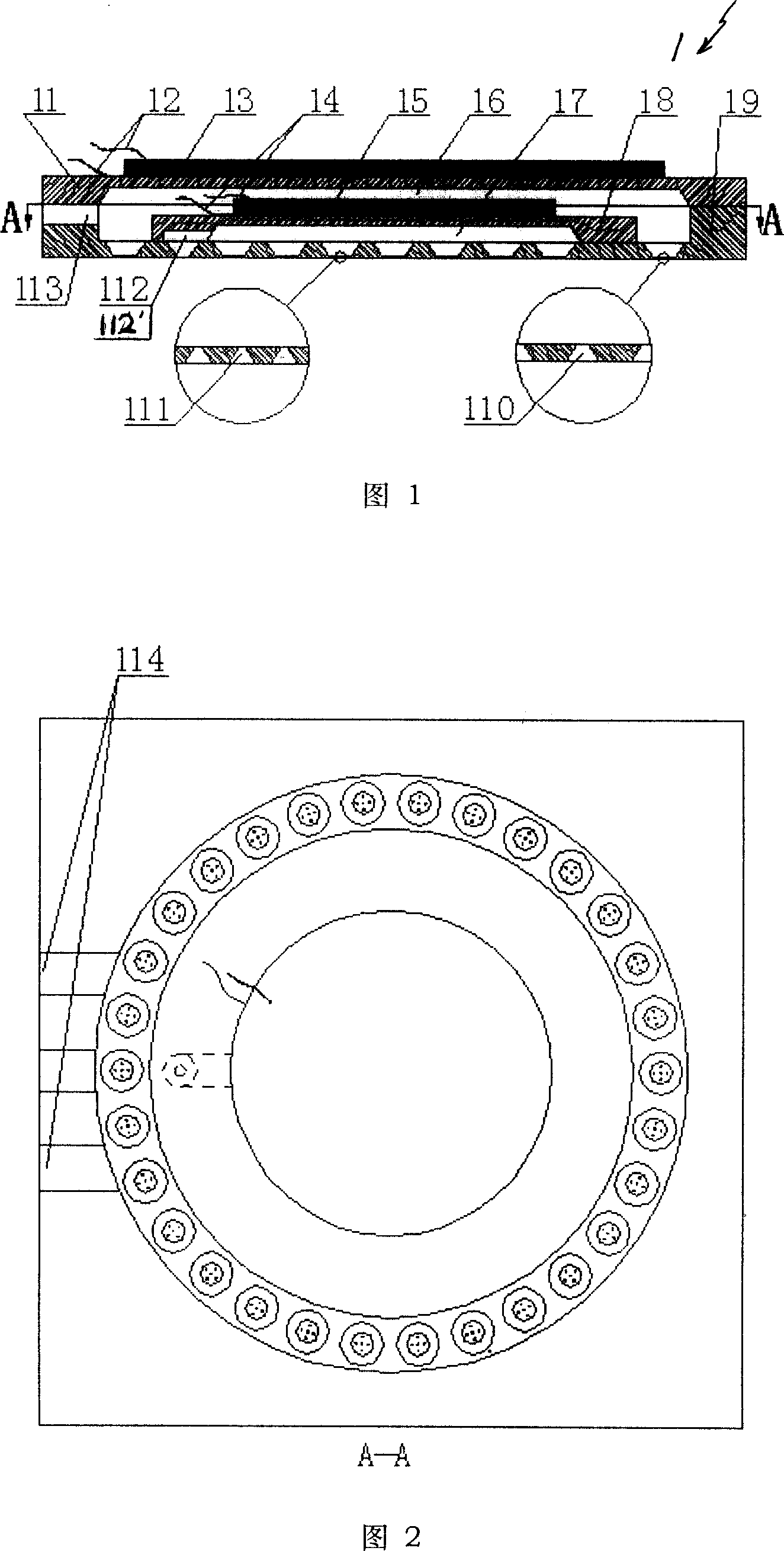
[0066] Embodiment 1: Please refer to Fig. 1 to Fig. 5, first please refer to Fig. 1;
[0067] The micro-spray device 1 is composed of an inner micro-spray and an outer micro-spray, and the inner micro-spray is set inside the outer micro-spray;
[0068] The microspray device 1 includes an outer vibration substrate 11, an outer piezoelectric ceramic sheet lead 12, an outer piezoelectric ceramic sheet 13, an inner piezoelectric ceramic sheet lead 14, an inner piezoelectric ceramic sheet 15, an outer cavity body 16, and an inner cavity Body 17, inside vibrating substrate 18, orifice film 19, on the orifice film 19, be provided with gas micro-injection hole 110, on the orifice film 19, be provided with lubricant micro-injection hole 111, lubricant inlet 112, gas inlet 113, leading wire opening 114;
[0069] The outer micro-spray is composed of an outer vibrating substrate 11, an outer piezoelectric ceramic sheet lead 12, an outer piezoelectric ceramic sheet 13, an outer cavity 16,...
Embodiment 2
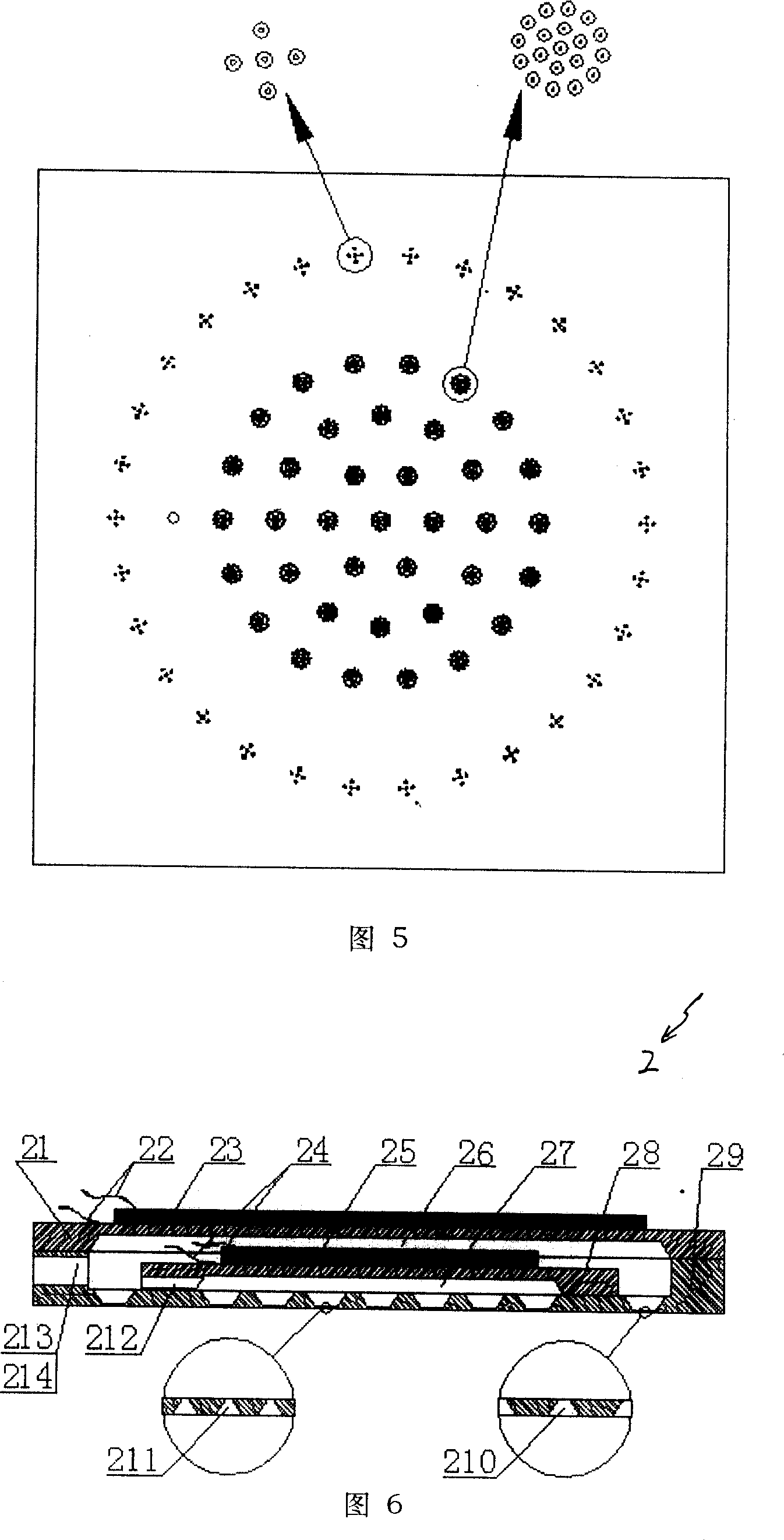
[0077] Please refer to shown in Fig. 6; Its difference with embodiment one is that the lubricant inlet 212 is opened on the inner vibrating substrate 28, and this micro-spraying device 2 includes the outer vibrating substrate 21, the outer piezoelectric ceramic sheet lead wire 22 , the outer piezoelectric ceramic sheet 23, the inner piezoelectric ceramic sheet lead wire 24, the inner piezoelectric ceramic sheet 25, the outer cavity body 26, the inner cavity body 27, the inner side vibrating substrate 28, the nozzle hole film 29, on the nozzle hole film 29 A gas micro-spray hole 210 is provided, and a lubricant micro-spray hole 211 , a lubricant inlet 212 , a gas inlet 213 , and a lead port 214 are arranged on the nozzle film 29 .
[0078] The second embodiment is also composed of inner and outer micro-sprays, and the inner micro-spray is set inside the outer micro-spray;
[0079] The outer micro-spray is composed of an outer vibrating substrate 21, an outer piezoelectric ceram...
Embodiment 3
[0086] Please refer to Fig. 7; the difference between it and the first embodiment is that the lubricant inlet 312 on the inner cavity 37 is opened on the nozzle hole film 39, thus avoiding the nesting structure, and the assembly is relatively simple.
[0087] This microspray device 3 comprises outer vibrating substrate 31, outer piezoelectric ceramic sheet lead wire 32, outer piezoelectric ceramic sheet 33, inner piezoelectric ceramic sheet lead wire 34, inner piezoelectric ceramic sheet 35, outer cavity body 36, inner cavity Body 37, inner side vibrating substrate 38, nozzle hole film 39, gas micro nozzle hole 310 is provided on nozzle hole film 39, lubricant micro nozzle hole 311, lubricant inlet 312, gas inlet are provided on nozzle hole film 39 313.
[0088] The micro-spray device 3 is also composed of two micro-sprays inside and outside, and the inside micro-spray is set inside the outside micro-spray;
[0089] The outer micro-spray is composed of an outer vibration subs...
PUM
 Abstract
Description
Claims
Application Information