
Deepwater drilling device based on near surface deviation

A deepwater drilling and drilling platform technology, which is applied in underwater drilling, earthwork drilling, wellbore/well components, etc. It can solve the problems that the ABS system cannot bear the flow rate, the system stability is not good, and the system requirements are high, so as to achieve improvement. Stability and adaptability, increased operating window, and improved adaptability

Active Publication Date: 2008-01-23
CHINA NAT OFFSHORE OIL CORP +1
View PDF7 Cites 19 Cited by
  • Summary
  • Abstract
  • Description
  • Claims
  • Application Information

AI Technical Summary

Problems solved by technology

However, this ABS system has the following disadvantages: 1. Due to the influence of the force state of the system, the ABS system cannot withstand too much flow velocity, and the buoys are installed in the deep water (250 meters to 300 meters), which not only has great requirements on the system. High and inconvenient to work
3. Due to the large size of the buoy, the installation operation is very time-consuming, the manufacturing cost is also high, and the water depth used is also limited. The maximum water depth is 1500 meters
4. Since the blowout preventer sits directly on the buoy, and the weight of the blowout preventer is very heavy, the center of gravity of the system composed of the buoy and the blowout preventer is high, and the stability of the system is not good, so it is harmful to the safety and operation of the system. had a great negative impact

Method used


Image

  • Deepwater drilling device based on near surface deviation
  • Deepwater drilling device based on near surface deviation
  • Deepwater drilling device based on near surface deviation

Examples


Embodiment Construction

[0019] The present invention will be described in detail below in conjunction with the accompanying drawings and embodiments.

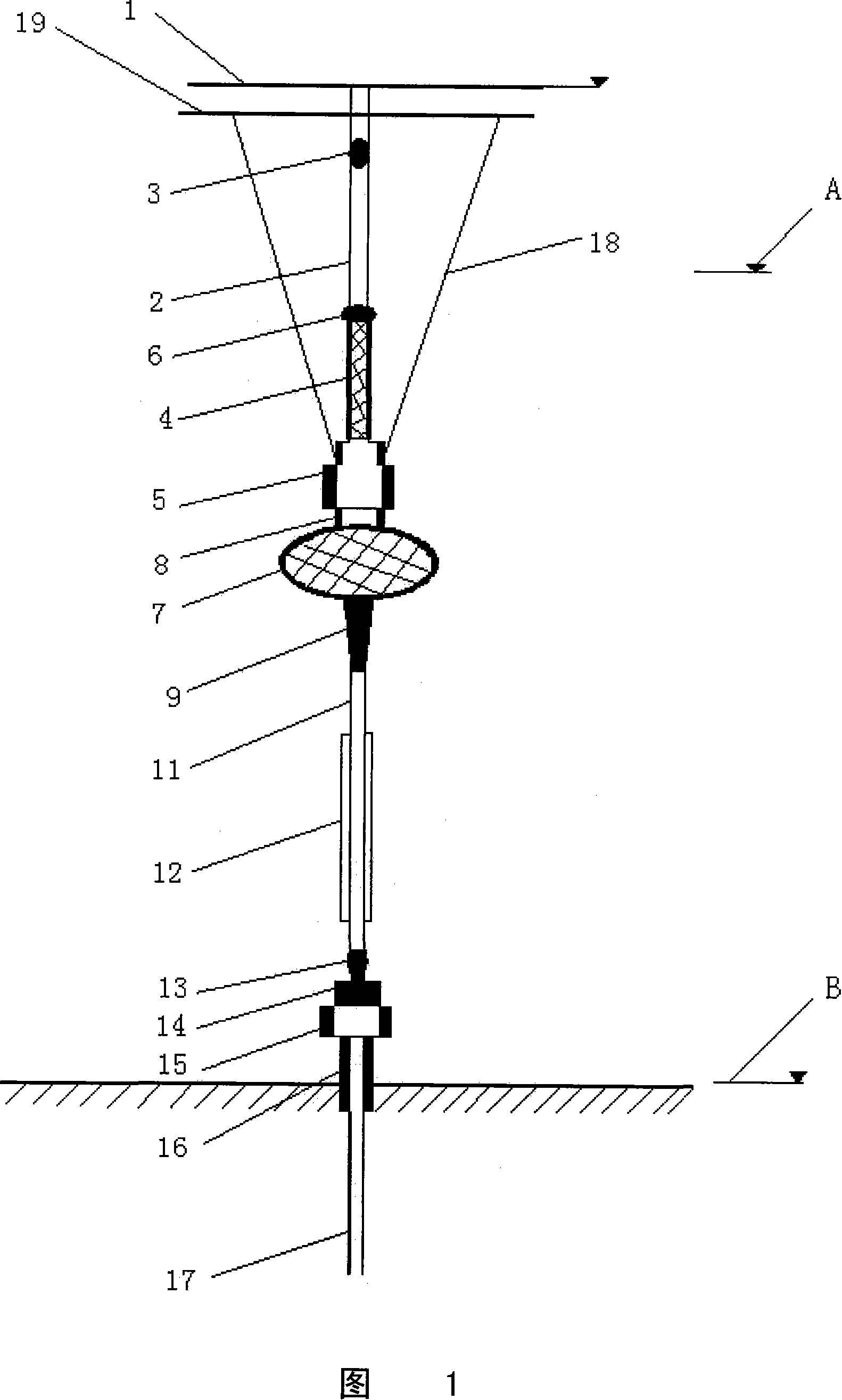
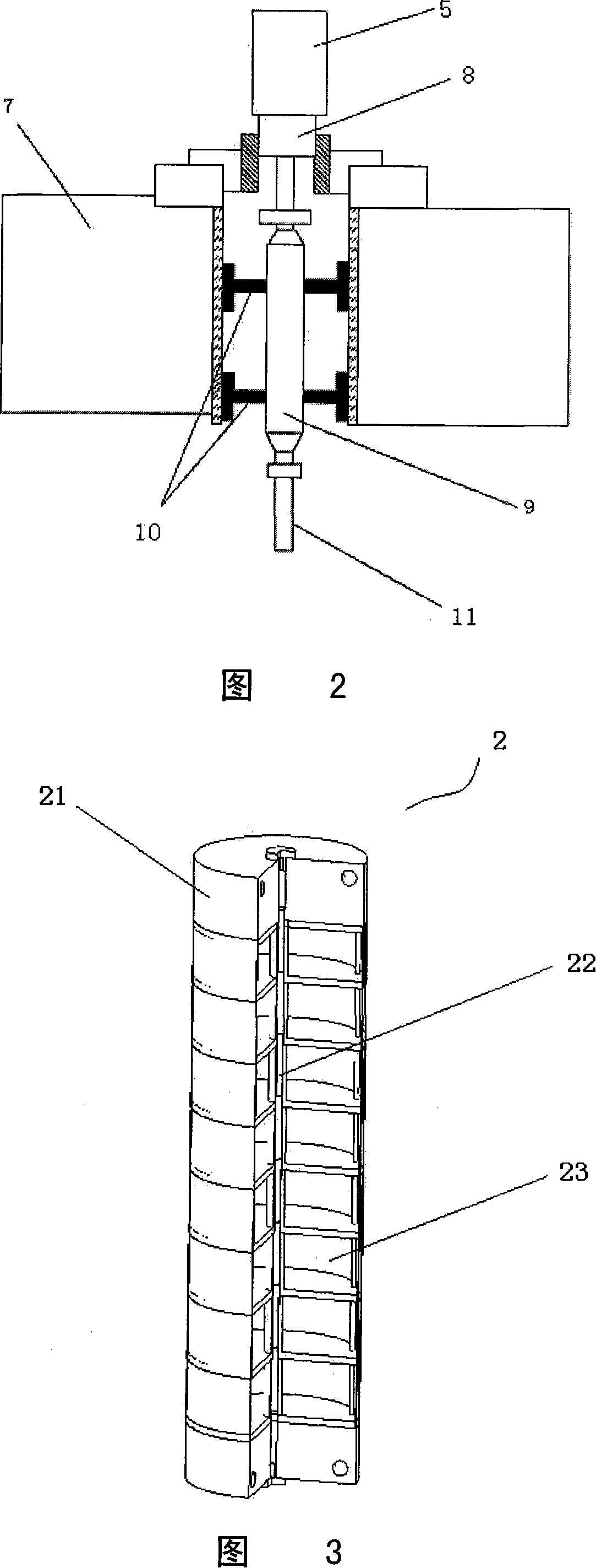
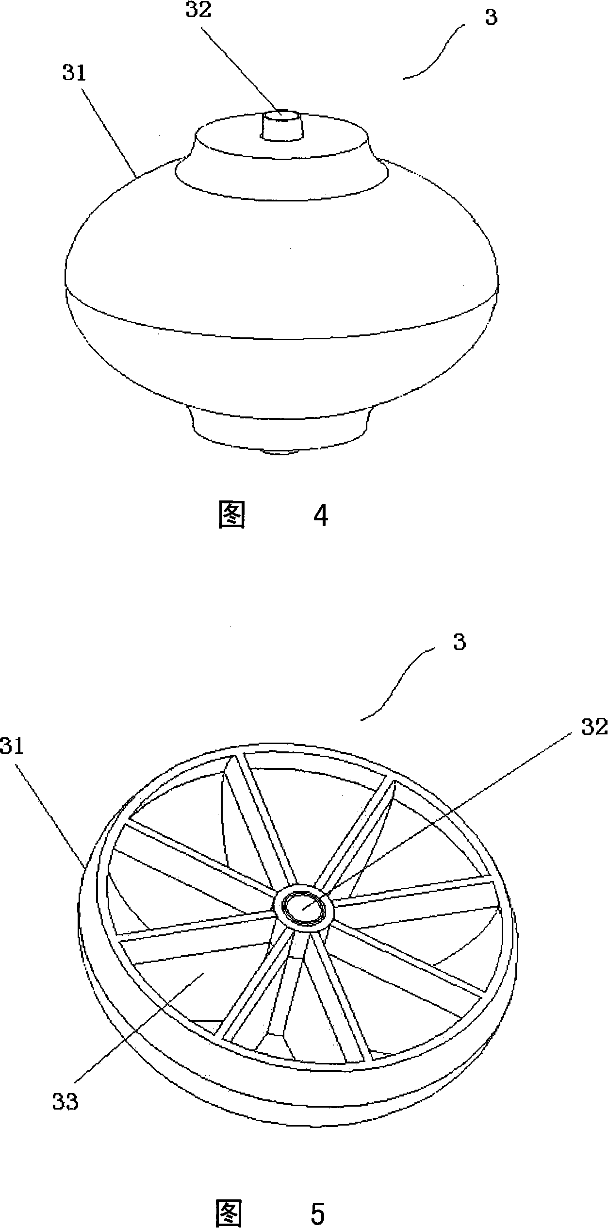
[0020] As shown in Fig. 1 and Fig. 2, the present invention includes a conventional riser 2 connected to the drilling platform 1, an upper flexible joint 3 is arranged in the middle of the riser 2, the riser 2 passes through a buoyancy chamber 4, and a blowout preventer The blowout preventer 5 is installed at a place 80-100m below the water surface A. The upper end of the buoyancy chamber 4 is provided with a disconnecting device 6 from the riser 2. A ballast tank 7 and an upper wellhead are provided below the blowout preventer 5. 8 is located between the blowout preventer 5 and the ballast tank 7 and sits and hangs in the central axis hole of the ballast tank 7 . The upper end of a stress joint 9 goes deep into the central shaft hole of the ballast tank 7 and is connected with the upper wellhead 8 , and a centralizer 10 is arranged between the stress...


PUM


Abstract

The invention relates to a deep-water well-drilling device that is based on near-water-level disengagement, which is characterized in that, the drilling device comprises a water-isolating pipe connected with a well-drilling platform; in the middle of the water-isolating pipe, an upper flexible joint is arranged; the water-isolating pipe passes a float cabin and is connected with a blowout preventer; the upper end of the float cabin is connected with the water-isolating pipe through a disengaging mechanism; below the blowout preventer, a ballast tank is arranged; between the blowout preventer and the ballast tank, an upper wellhead is placed; the upper end of a stress joint connected with a centering guide goes deeply into the ballast tank and is connected with the upper wellhead, and the lower end of the stress joint is connected with a hi-pressure water-isolating pipe, out of which a float block is provided; the bottom end of the hi-pressure water-isolating pipe is connected in sequence with a lower flexible joint, a lower wellhead, a conduit and a casing pipe; the conduit and the casing pipe are fixed in the seabed; between the perimeter of the blowout preventer and the lower part of the opening of the moon pond of the well-drilling platform, at least three centering ropes are connected. The invention is of high applicability, steady performance, is convenient to disengage the water-isolating pipe, and can be widely used in deep-water well drilling.

Description

technical field [0001] The invention relates to an offshore oil drilling device, in particular to a deep water drilling device based on detachment near the water surface. Background technique [0002] There are generally three types of deepwater drilling devices, including conventional drilling devices with a blowout preventer (BOP) placed on the seabed mud line, drilling devices with a blowout preventer in water, and drilling devices with a blowout preventer on water. [0003] In conventional drilling equipment, the blowout preventer is placed on the seabed, and the drilling ship and the subsea wellhead are connected by a riser. With the increase of water depth, the conventional underwater drilling method with BOP is facing great challenges. On the one hand, as the water depth increases, longer risers and drill pipes are required, which will consume more mud and equipment with higher pressure levels, and the weight and size of risers and blowout preventers will also increa...

Claims


Application Information

Patent Timeline
Patent Type & Authority Applications(China)
IPC IPC(8): E21B7/12E21B33/064
Inventor 姜伟蒋世全许亮斌
Owner CHINA NAT OFFSHORE OIL CORP
Learn More