Method for soldering spiral welded pipe

A spiral welded pipe and welding technology, which is applied in welding equipment, manufacturing tools, metal processing equipment, etc., can solve the problems of high internal and external quality of the weld, frequent adjustment of the position of the welding torch head, and welding offset welding seam forming quality. Achieve stable and reliable welding process, avoid excessive welding seam height, and ensure the effect of welding seam quality

Inactive Publication Date: 2008-01-30
冯白茹
View PDF1 Cites 9 Cited by
  • Summary
  • Abstract
  • Description
  • Claims
  • Application Information

AI Technical Summary

Problems solved by technology

[0004] The present invention aims to solve the problems that the seam reinforcement of the precision internal welding seam in the traditional spiral welded pipe welding is too large, the position of the torch head is frequently adjusted during the precision internal welding, the welding deviation is easy to occur, and the quality of the weld seam is unstable. Therefore, a method of the present invention is provided. A spiral welded pipe welding method, the spiral welded pipe welded by the method of the present invention, the labor intensity of the welder is low, the internal quality and appearance quality of the weld seam are high, and the weld reinforcement can be controlled at an appropriate height

Method used


Image

  • Method for soldering spiral welded pipe
  • Method for soldering spiral welded pipe

Examples


Embodiment 1

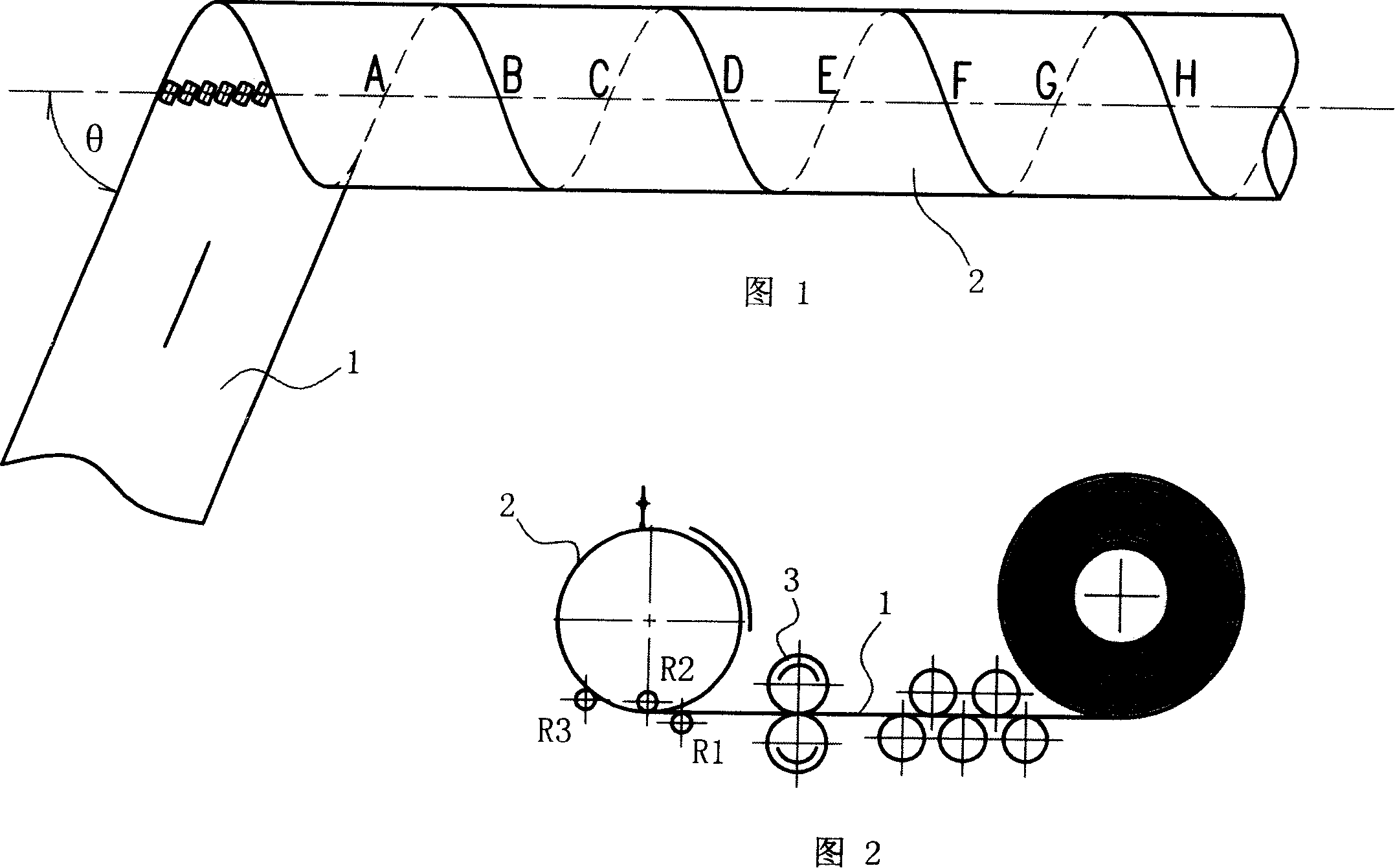
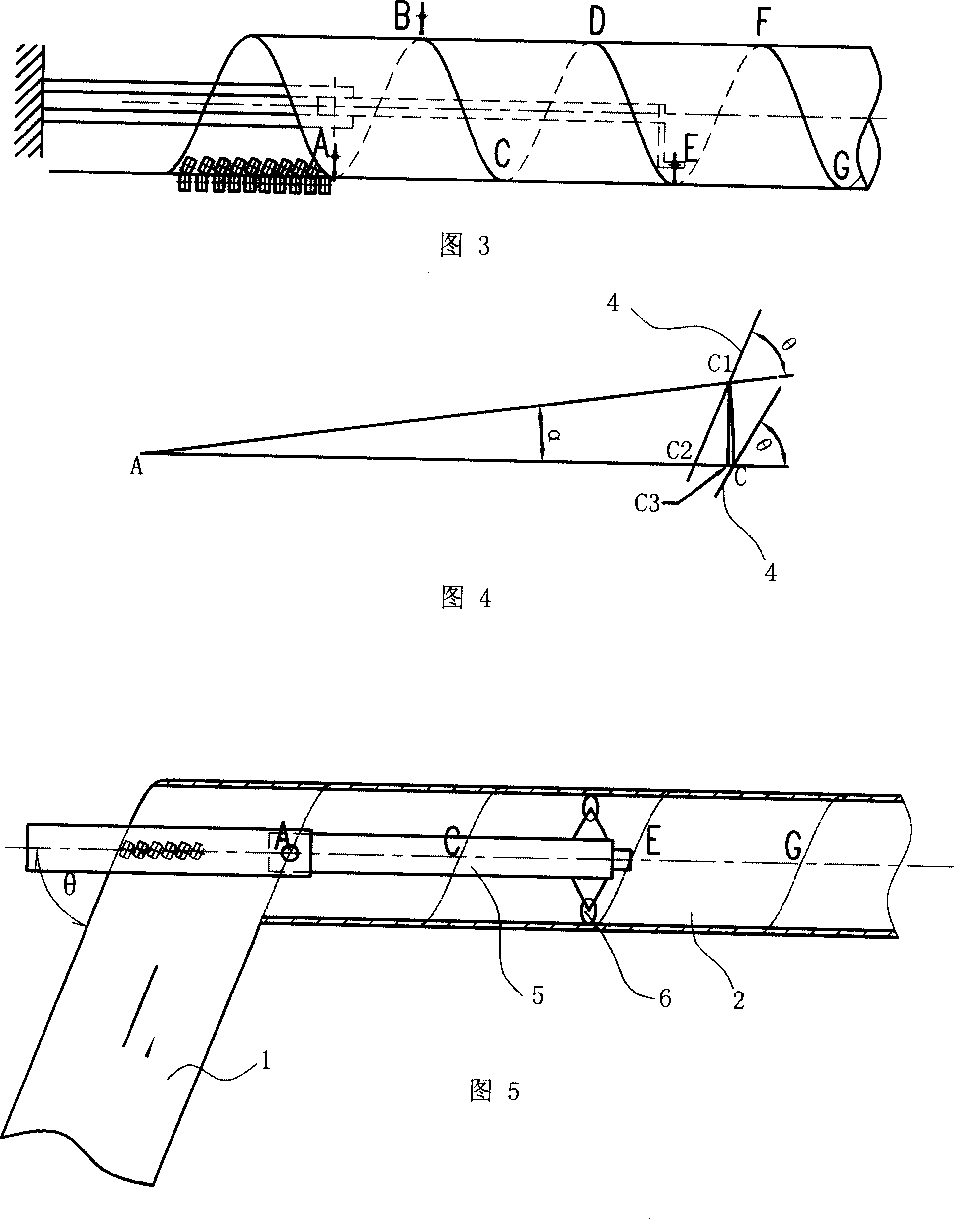
[0021] A spiral welded pipe welding method, comprising continuously sending the steel strip to the spiral welded pipe former according to the helix angle θ, and setting the first internal welding torch at the initial position A of the spirally formed pipe of the steel strip to form the steel strip The spiral seam is pre-welded, and an external welding torch is installed at part II B, which is half a pitch away from the I place A in the extension direction of the spiral welded pipe, to perform external welding on the spiral seam of the steel strip; in the extension direction of the spiral welded pipe, it is A The second internal welding torch is set at the position III of the two pitches to carry out fine internal welding on the steel strip spiral seam. The front end of the bracket 5 is provided with four rollers 6 that can rotate according to the tangential direction of the inner wall of the spirally rotated spiral welded pipe, and the four rollers are distributed along the cir...

Embodiment 2

[0023] The difference between this example and the previous example is that the beveling equipment is set at C, which is one pitch away from the I place A in the extension direction of the spiral welded pipe, and the bevel is reprocessed for the pre-internal welding seam to make it U-shaped or V-shaped. Shaped groove, as in the above example, fine internal welding is welded in the groove.

Embodiment 3

[0025] What this example is different from Example 1 is that the outer welding torch is set at the D place where the spiral welded pipe extension direction is one and a half pitch away from the said I place A to carry out external welding to the spiral seam of the steel strip; Three pitch places G at I place A carry out precision internal welding, and correspondingly, the pendulum support 5 stretches a distance relative to Example 1 so that the second internal welding torch is positioned at G place.


PUM


Abstract

A spiral welding pipe welding method with simple and convenient manufacture process and high welding quality includes that the metal strip is continuously fed to a spiral welding pipe shaper by the spiral angle theta and the pre-internal welding of a spiral seam formed by the steel strip is carried out by a first internal welding gun arranged at the initial position I (A) of the steel strip spiral forming pipe. The invention is characterized in that an external welding gun is arranged at the position about odd-number times pitch away from the position I (A) in the extension direction of the spiral welding pipe to carry out the external welding to the steel strip spiral seam; a secondary internal welding gun is arranged at the position III (E) at least two pitches away from the position I (A) in the extension direction of the spiral welding pipe to carry out the finishing internal welding to the steel strip spiral seam. The invention is suitable for manufacturing the spiral steel pipes.

Description

technical field [0001] The invention relates to a method for manufacturing welded steel pipes, in particular to a method for manufacturing spiral welded pipes. Background technique [0002] Spiral welded pipe is formed by spiral coil welding of steel strip, and its spiral seam is welded by double-sided automatic submerged arc welding. As shown in Figure 1 and Figure 2, the production principle is as follows: On the production line of the spiral welded pipe unit (referred to as "online"), the steel strip 1 drawn from the raw steel strip coil and leveled is placed on the steel strip delivery roller 3 Under the influence, it is continuously sent to the former according to the helix angle θ. Under the action of the three-axis row wheels R1, R2 and R3 of the former, the steel strip is bent and rolled into a spiral cylinder. The non-walking torch head is always aligned with the spiral seam line for welding, and the relative motion is generated during the spiral rotation of the st...

Claims


Application Information

Patent Timeline
Patent Type & Authority Applications(China)
IPC IPC(8): B21C37/12B23K31/00
CPCB21C37/121
Inventor 冯白茹
Owner 冯白茹
Why Eureka
Try Eureka