Flow quantity self-adjusting jetting stream vacuum generator

A vacuum generator and vacuum generation technology, which is applied in jet pumps, non-displacement pumps, machines/engines, etc., can solve problems such as inability to adapt to complex working conditions, increase user costs, and inability to adjust the flow rate of vacuum nozzles, etc., to achieve reduction Small effective cross-sectional area, automatic adjustment, and reduced air consumption

Inactive Publication Date: 2008-01-30
NANJING UNIV OF SCI & TECH
View PDF1 Cites 17 Cited by
  • Summary
  • Abstract
  • Description
  • Claims
  • Application Information

AI Technical Summary

Problems solved by technology

However, this parallel vacuum generating device cannot adapt to various complex working conditions in production because there are only two sizes of nozzles.
Although the patent application CN200510050203 proposes a reconfigurable modular design, it is proposed to obtain the same series of vacuum

Method used


Image

  • Flow quantity self-adjusting jetting stream vacuum generator

Examples


Embodiment Construction

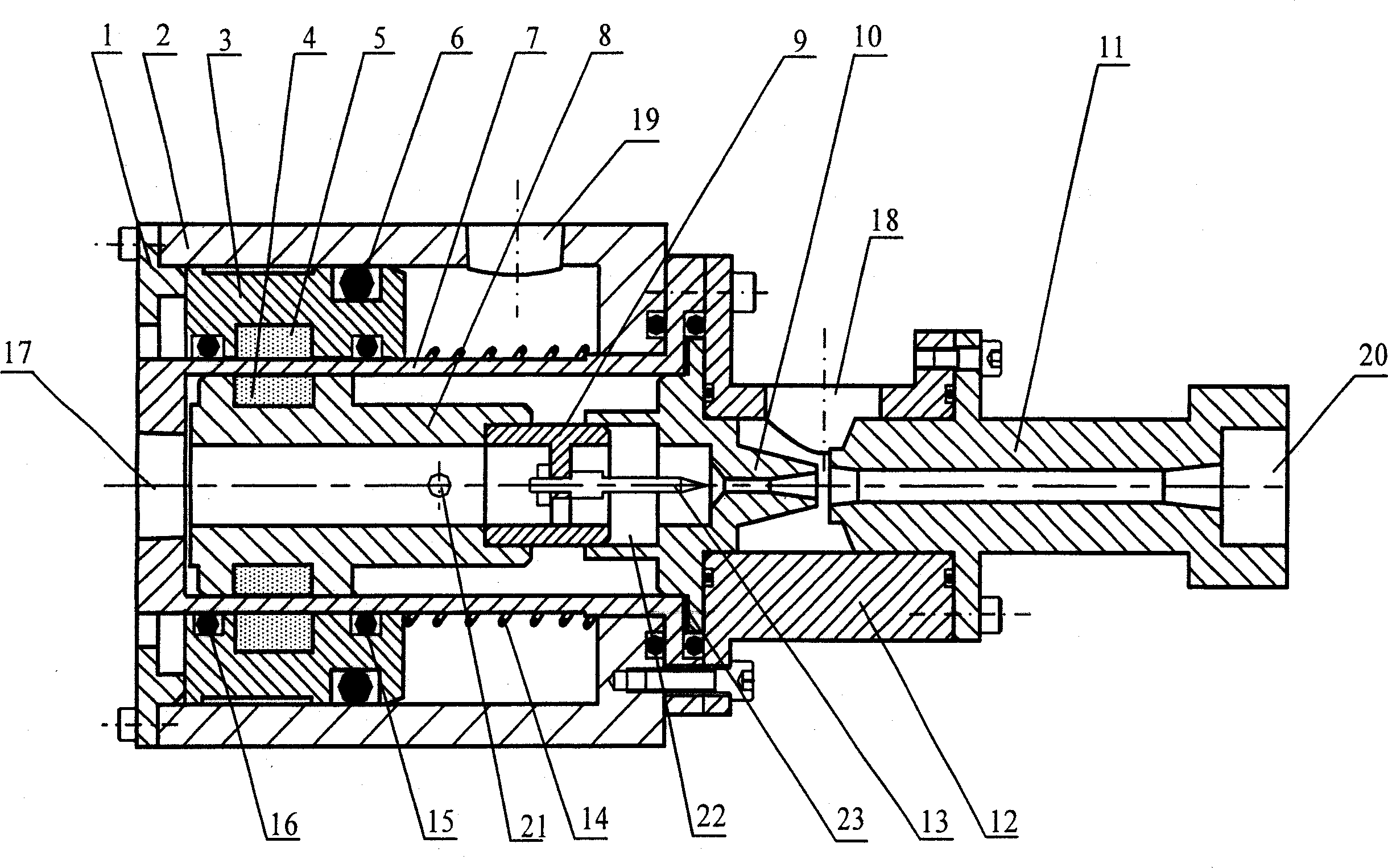
[0009] The present invention will be described in further detail below in conjunction with the accompanying drawings.

[0010] With reference to the accompanying drawings, the flow self-regulating jet vacuum generator of the present invention includes a flow self-regulating part and a vacuum generating part, and the flow self-regulating part is located at the front end of the vacuum generating part. Wherein, the vacuum generating part includes a nozzle 10, a receiving pipe 11 and a connecting pipe 12 connecting the nozzle 10 and the receiving pipe 11. The connecting pipe 12 is provided with a vacuum port 18 that can be connected with a vacuum suction cup. The nozzle 10 and the receiving pipe The tube 11 constitutes the gas flow passage of the vacuum generating portion, and the inner walls of the nozzle 10, the receiving pipe 11 and the connecting pipe 12 constitute a vacuum chamber. The flow self-regulating part includes a master cylinder and a slave cylinder. The master cylin...


PUM


Abstract

The invention discloses a flow auto-adjustment jet flow vacuum generating device, comprising a section of flow auto-adjustment and a vacuum generating section. A needle valve used for adjustment is positioned at the front of a jet nozzle throat of the vacuum generating section. Meanwhile the needle valve can feed back the vacuum pressure to a right cavity of an active cylinder of the vacuum generating device to make a pressure difference between the right cavity and a left cavity of the active cylinder which is communicated with the atmosphere to drive the active valve and to drive the passive valve through magnetic driving, finally to drive the needle valve which is fixedly connected with the passive valve to move. The invention not only realizes the dual purposes of fast response in vacuum and saving energy sources, but also realizes the auto adjustment to the flow of air supply for the position of the needle valve can be adjusted according to vacuum level. Meanwhile, if the vacuum level changes, the needle valve can look for a new balance point automatically. Thus the vacuum generating device has the function of automatic adjustment of the air supply flow and is suitable for various working conditions.

Description

a technical field [0001] The invention relates to a vacuum generating device, in particular to a flow self-regulating jet vacuum generator. Two background technology [0002] At present, there are two types of vacuum generators commonly used: vacuum pumps and vacuum generators. The vacuum generator is composed of a Laval nozzle that contracts first and then expands, a vacuum chamber and a receiving tube, and has an air supply port, an exhaust port and a vacuum port. When the gas supply pressure is higher than a certain value, a supersonic jet is ejected from the Laval nozzle, and under the effect of gas viscosity, the high-speed jet entrains the gas in the vacuum chamber to form a very low vacuum degree in the vacuum chamber. When the air supply pressure is constant, it can be approximately considered that the flow rate of the air supply is directly proportional to the effective cross-sectional area of ​​the nozzle. Compared with vacuum pumps, vacuum generators have been w...

Claims


Application Information

Patent Timeline
IPC IPC(8): F04F5/20F04F5/48
Inventor 李小宁滕燕赵萍萍路建萍
Owner NANJING UNIV OF SCI & TECH
Why Eureka
Try Eureka