Direct backheating burned flame type heating stove and working method

A heating furnace, direct technology, applied in the direction of combustion method, combustion type, combustion equipment, etc., can solve the problems of furnace pressure fluctuation, shorten the life of the furnace body, increase the furnace accident rate, etc., achieve precise automatic control and adjustment, and reduce furnace accidents efficiency, and the effect of improving the furnace operating rate

Inactive Publication Date: 2008-01-30
NORTH CHINA UNIVERSITY OF SCIENCE AND TECHNOLOGY
View PDF0 Cites 7 Cited by
  • Summary
  • Abstract
  • Description
  • Claims
  • Application Information

AI Technical Summary

Problems solved by technology

[0004] (1) Since each reversing process has to go through the process of "cutting off the gas --- reversing --- re-inputting the gas", each reversing will make the flame in the furnace disappear once, and the fire extinguishing time is generally about three minutes , the frequent extinguishing and ignition of the flame caused the frequent fluctuation of the furnace temperature, which not only caused the frequent drop of the heat transfer temperature and pressure, resulting in the reduction of the heat transfer rate, but also made the working temperature of the entire furnace lining change frequently, causing the temperature stress of the furnace lining to increase, which is easy to cause The furnace lining is cracked, and smoke and fire are everywhere, which increases the accident rate of the furnace, reduces the operation rate of the furnace, shortens the life of the furnace body, and seriously affects the normal operation and production process of the furnace.
[0005] (2) The reversing process causes large fluctuations in the furnace pressure
The large and frequent fluctuations of the furnace pressure make it more difficult for the automatic control system of the heating furnace to control the pressure, and the furnace pressure of the heating furnace cannot be kept working under a certain stable value for a long time, which makes the working process of the heating furnace not stable enough and prone to combustion conditions Various problems such as inability to adjust accurately
[0006] (3) The regenerator itself works at a very high temperature, and the frequent reversing causes the temperature of the regenerator to change frequently and violently. Under the action of high temperature and huge thermal shock, the regenerator often melts, softens, deforms, and ruptures , blockage and other issues
After the problem of the honeycomb body, the smoke exhaust, fuel and air supply were blocked, which seriously affected the production
[0007] (4) When the heating furnace is reversing, the gas in the pipeline between the reversing valve and the nozzle will be drawn out of the furnace, resulting in fuel loss. The shorter the reversing period, the greater the loss
[0008] (5) Since in the regenerative combustion method, the combustion is basically carried out under unstable conditions, this greatly increases the complexity of the combustion process, heat transfer process, and gas flow process in the furnace, and the production conditions Complex and diverse, it is difficult to establish a more accurate heating model that is consistent with the actual production. Because of this, the automatic control and automatic adjustment levels of most heating furnaces are very low, although the input rate of the automatic control system is very low. High, but the utilization rate is very low, and sometimes even completely abandon the automatic control to manual control, so that the accident rate of the heating furnace rises sharply, and the furnace operation rate drops sharply
[0009] From the above analysis, it can be seen that frequent reversing is the direct cause of unstable regenerative combustion process, high furnace accident rate and low furnace operation rate

Method used


Image

  • Direct backheating burned flame type heating stove and working method
  • Direct backheating burned flame type heating stove and working method

Examples


Embodiment Construction

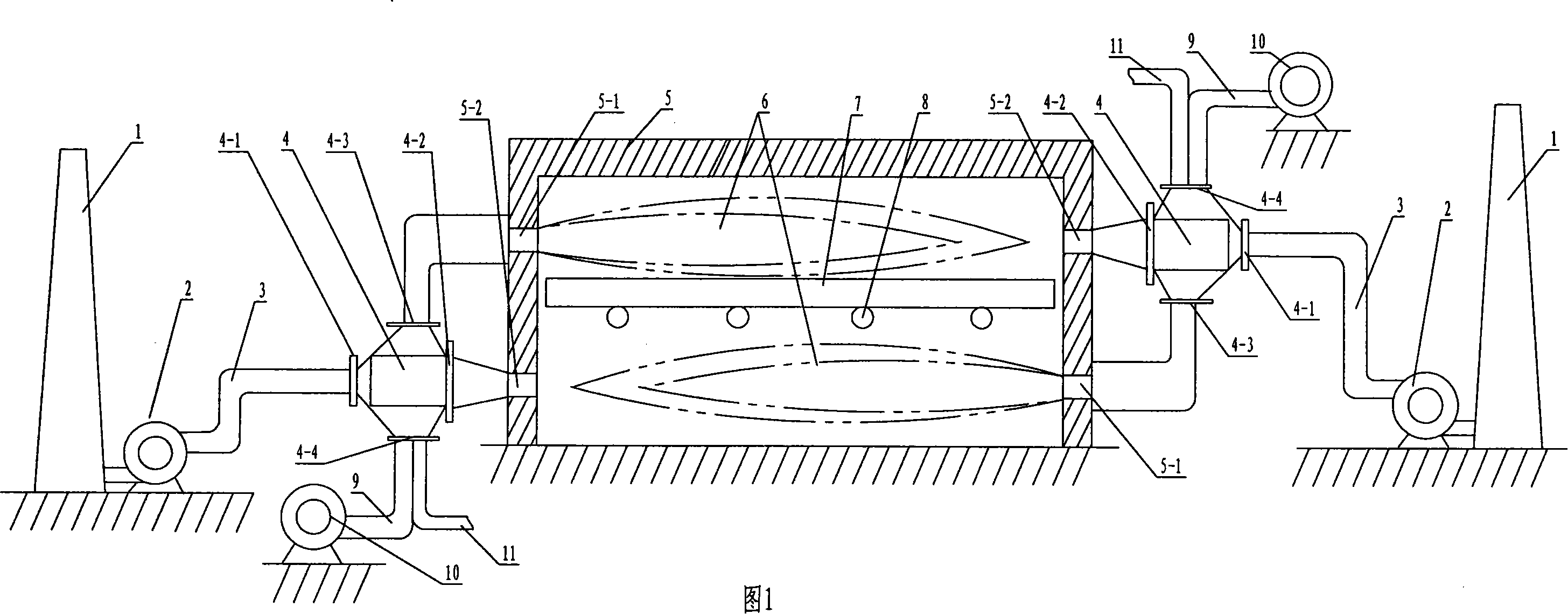
[0022] Referring to Fig. 1, the composition of the flame type heating furnace of direct regenerative combustion of the present invention comprises furnace body 5, heat exchange device, air supply device and smoke exhaust device, and the two sides of furnace body 5 are respectively provided with air fuel inlet 5-1 and The high-temperature flue gas outlet 5-2, wherein the air fuel inlet on each side is set corresponding to the position of the high-temperature flue gas outlet on the other side. The working status of the two ports on the same side of the heating furnace body is different, and when the upper port on one side is in the state of exhausting smoke, the lower port is in the state of fuel and air supply, while the upper port on the other side is in the state of fuel and air supply. The lower port is in the state of exhausting smoke. The smoke exhaust device is composed of a flue 3, an induced draft fan 2, and a chimney 1 connected to each other, and the air supply device...


PUM


Abstract

A flame-typed heating furnace by directly regenerative combustion and a working method pertain to the heating furnace technical field, and are used for solving the problem of constant switch in working state of the existing regenerative type heating furnaces. The invention comprises a furnace body, a heat-exchange device, an air-supply device and a smoke-exhaust device. The invention is characterized in that an air fuel inlet and a high-temperature smoke outlet are separately positioned at the two sides of the furnace body, and the air fuel inlet of one side is positioned correspondingly with the high-temperature smoke outlet on the other side. The working state of each opening of the furnace body in the invention needs not switch, thereby, the working state is stable. The invention still uses a high-temperature smoke exhausting method, but the heat-exchange process adopts a method of direct regeneration, thereby needing no commutation, and furnace temperature and furnace pressure are no longer frequently fluctuated, the combustion process in the furnace is very stable, therefore, the problems of easy cracking and pre-heater smelting, softening, deforming, breaking, blocking of the furnace body are solved. The furnace failure rate is greatly decreased, and the working rate is improved, both of which provide strong and powerful technical support for stable and continuous production of the heating furnace.

Description

technical field [0001] The invention relates to a flame type heating furnace with a high-temperature flue gas waste heat recovery device and a working method of the heating furnace, belonging to the technical field of heating furnaces. Background technique [0002] At present, known flame heating furnaces with high-temperature flue gas waste heat recovery systems use regenerative combustion technology. The regenerative combustion technology integrates the heat storage system, smoke exhaust system, combustion system and furnace structure. The heat storage system, smoke exhaust system and combustion system are symmetrically arranged on both sides of the furnace body. When one side is in the smoke exhaust state (heat cycle), the other side is in the fuel supply state (cold cycle), and the state of both sides is switched after a period of time. When the regenerator is in the state of exhausting smoke, the high-temperature flue gas flows through the regenerator and releases heat...

Claims


Application Information

Patent Timeline
Patent Type & Authority Applications(China)
IPC IPC(8): F27B3/18F27B3/26F27D17/00F23C5/00
Inventor 王子兵朱予东赵斌梁精龙邵淑华
Owner NORTH CHINA UNIVERSITY OF SCIENCE AND TECHNOLOGY
Why Eureka
Try Eureka