Microphone amplifier

A technology of amplifiers and operational amplifiers, applied in the direction of amplifiers, low-frequency amplifiers, improved amplifiers to reduce the harmful effects of internal resistance, etc., can solve the problems of increased noise floor, etc., to achieve reduced parasitic capacitance, good S/N, and noise floor produces a smaller effect

Inactive Publication Date: 2008-01-30
SANYO ELECTRIC CO LTD +1
View PDF2 Cites 1 Cited by
  • Summary
  • Abstract
  • Description
  • Claims
  • Application Information

AI Technical Summary

Problems solved by technology

However, if the amplification factor of the operational amplifier is increased, another problem of an increase in floor noise occurs.

Method used


Image

  • Microphone amplifier

Examples


Embodiment Construction

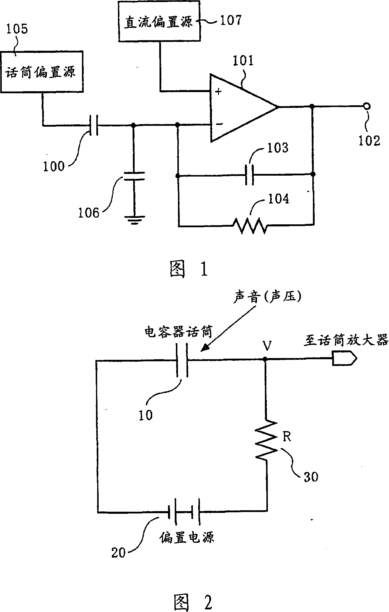
[0019] An embodiment of the present invention will be described in detail with reference to FIG. 1 . FIG. 1 shows a microphone amplifier of a condenser microphone according to this embodiment.

[0020] Fig. 1 comprises: condenser microphone (100), and sound is transformed into voltage signal; Operational amplifier (101), inverting input terminal (-) is applied the voltage signal from this condenser microphone (100), and positive phase input terminal (+) A DC bias voltage is applied; the feedback capacitor (103) is connected between the inverting input terminal (-) and the output terminal (102) of the operational amplifier (101); the feedback resistor (104) is connected between the between the inverting input terminal (-) and the output terminal (102) of the operational amplifier (101); and a microphone bias source (105) for providing a DC bias to the capacitor microphone (100).

[0021] The two input terminals of the operational amplifier (101) have parasitic capacitances cau...


PUM


Abstract

With a microphone amplifier using an operational amplifier, there has been a problem that a sensitivity of the condenser microphone is reduced by an influence of a parasitic capacitance generated at an input terminal of the operational amplifier. This invention offers a microphone amplifier having a condenser microphone that converts a sound into a voltage signal, an operational amplifier having an inverting input terminal to which the voltage signal from the condenser microphone is applied and a non-inverting input terminal to which a direct current bias voltage is applied, a capacitor connected between the inverting input terminal and an output terminal of the operational amplifier, and a resistor connected between the inverting input terminal and the output terminal of the operational amplifier.

Description

technical field [0001] The present invention relates to a microphone amplifier for amplifying a voice signal from a condenser microphone for converting voice into a voltage signal, and more particularly to a microphone amplifier for reducing the influence of parasitic capacitance generated during integrated circuit integration. Background technique [0002] Condenser microphones are known which convert sound into a voltage signal. Condenser microphones are made of capacitors. When the capacitance C of the capacitor in the formula of Q=C V (Q is the charge, C is the capacitance of the capacitor, and V is the voltage between the two ends of the capacitor) changes according to the sound, in a state of constant charge, the voltage between the two ends of the capacitor V changes, and according to this principle, sound is converted into a voltage signal. [0003] Figure 2 shows a schematic diagram of the working principle of a condenser microphone. A capacitor microphone 10 com...

Claims


Application Information

Patent Timeline
Patent Type & Authority Applications(China)
IPC IPC(8): H04R19/01H04R3/00H03F99/00
CPCH03F1/08H03F3/181H04R19/04H03F1/34H04R3/00H04R3/002
Inventor 铃木达也金田安弘
Owner SANYO ELECTRIC CO LTD
Why Eureka
Try Eureka