Overall view monitoring method and apparatus

A panoramic monitoring and equipment technology, which is applied in image data processing, television, instruments, etc., can solve problems such as difficulty in checking evidence beforehand, loss of key target detection, poor performance of low-speed translation, etc., to facilitate scene layout and improve timeliness , the effect of reducing requirements

Inactive Publication Date: 2011-07-20
无锡安科兴业科技有限公司
View PDF0 Cites 3 Cited by
  • Summary
  • Abstract
  • Description
  • Claims
  • Application Information

AI Technical Summary

Problems solved by technology

This kind of working mode can only achieve "clear sight" of one target in a period of time. In order to achieve a clear observation of multiple targets, polling must be used to achieve it. Polling will lead to target The information is incomplete, and in severe cases, it may even lead to the loss of detection of key targets, which brings great difficulties to the pre-event prevention and post-event verification of evidence
[0004] In addition, the PTZ camera's own shortcomings such as slow startup speed, poor low-speed translation performance, and no feedback also reduce the accuracy and reliability of target detection and tracking

Method used


Image

  • Overall view monitoring method and apparatus
  • Overall view monitoring method and apparatus
  • Overall view monitoring method and apparatus

Examples


Embodiment Construction

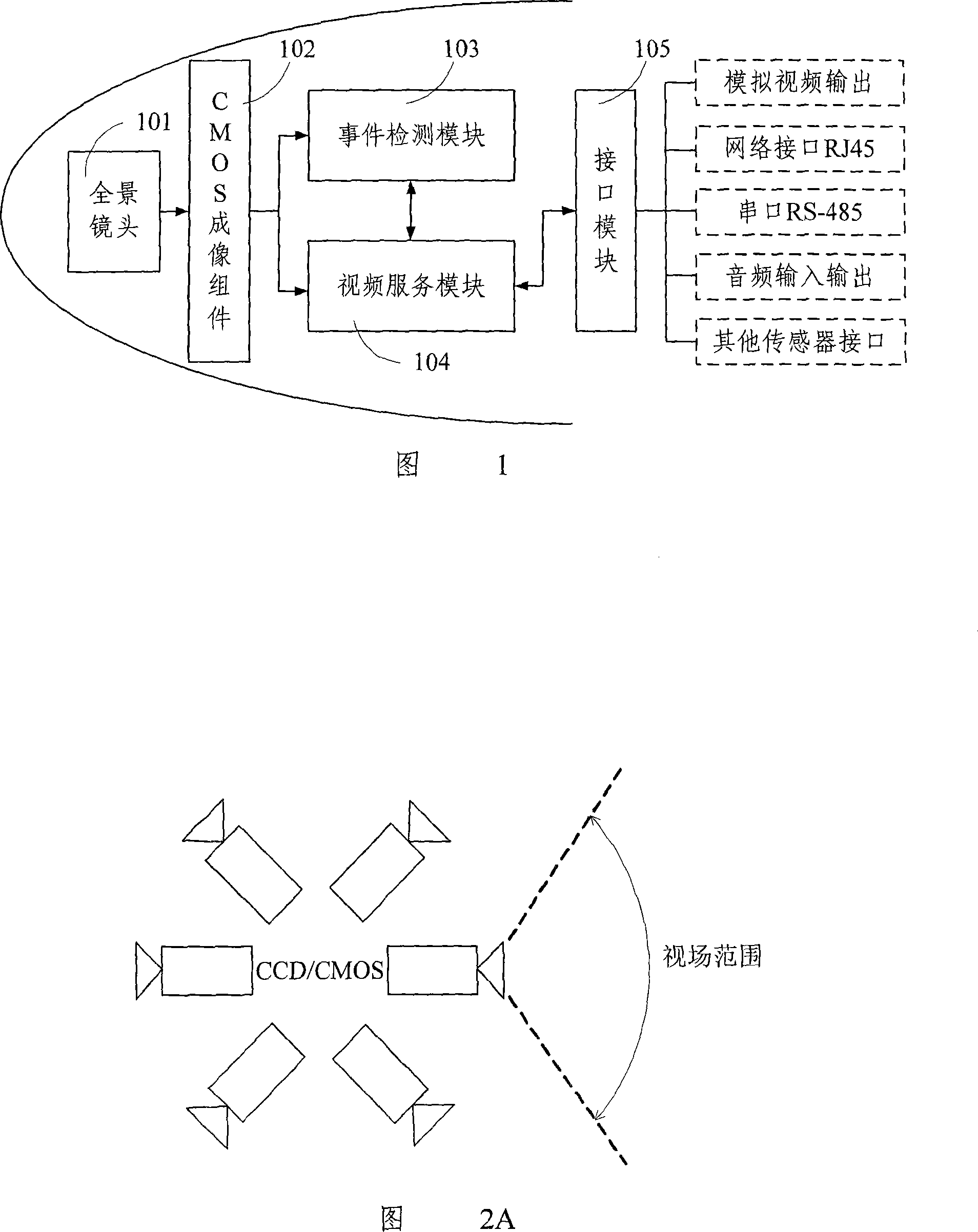
[0059] FIG. 1 is a structural schematic diagram of a panoramic surveillance device in the present invention. As shown in FIG.

[0060] The panoramic lens 101 has high-resolution characteristics, and its field of view can cover a 360° panoramic space of the monitoring site. The CMOS imaging component 102 has the advantages of small size, high integration, low power consumption, etc., and compared with CCD imaging, using the CMOS imaging component can greatly save costs, and more importantly, the CMOS imaging component directly outputs digital video signals without the need for analog / The subsequent intelligent image analysis can be directly carried out through digital conversion, which improves the real-time performance. The panoramic lens 101 and the CMOS imaging component 102 are combined to form a panoramic video sensor device, which is a high-resolution front-end imaging device with an ultra-wide field of view, which can monitor the monitoring site at 360° without blind sp...


PUM


Abstract

The present invention relates to a panorama monitoring method and device, wherein, the panorama camera lens and the imaging component are combined to get the panorama video frequency information of the monitoring scene, and the affair checking module is used for holding intelligent image analyzing for the panorama video frequency information, and according to the obtained intelligent analyzing result to judge whether having the affair to produce in accordance with the advancedly setting alarming condition, and producing affair checking report. The video frequency module is used for using the intelligent analyzing result to realize multi-aim suppositional PTZ following and providing a repeatedly used processing and transmission mechanism for the resolution aiming image, which not only solves the problem of seeing clearly and seeing fully, but also effectively reduces the requirement for the transmission belt width to realize high effective transmission. The interface module is used forapplying all the interfaces for the connecting of panorama monitoring device and the outside. According to the proposal of the present invention, the present invention realizes continuously monitoring 360 degrees panorama space without missing out or missing any accident affair, realizing the intelligent monitoring without blind point and dead angle.

Description

technical field [0001] The invention relates to video monitoring technology, in particular to a panoramic monitoring method and equipment. Background technique [0002] The current panoramic monitoring equipment is mainly composed of panoramic lens and CCD / CMOS imaging components. The analog video signal output is connected to the panoramic video server, and the panoramic video server transmits the unfolded image to the monitoring room or directly to the monitor for monitoring. show. For the remote monitoring system, the panoramic video server not only needs to complete the unfolding of the image, but also needs to realize the video compression and transmission. The work pressure is high, and the real-time performance of the monitoring is reduced. [0003] Panoramic camera is a new type of monitoring equipment. Without using multiple cameras, one panoramic camera can realize 360° blind spot monitoring of a large space. Due to the limitation of the resolution of closed-circu...

Claims


Application Information

Patent Timeline
Patent Type & Authority Patents(China)
IPC IPC(8): H04N7/18H04N7/26G03B37/00G06T7/20H04N19/59
Inventor 王占宁菅云峰蔡成曾建平孙楠
Owner 无锡安科兴业科技有限公司
Why Eureka
Try Eureka