Biometric identification apparatus

一种活体认证、手指放置的技术,应用在检测活手指形、使用光进行诊断、传感器等方向,能够解决脉搏信号小、很难脉搏和噪音分离、检测脉搏困难等问题,达到简单构造的效果

Inactive Publication Date: 2008-02-13
HITACHI MEDIA ELECTORONICS CO LTD
View PDF2 Cites 20 Cited by
  • Summary
  • Abstract
  • Description
  • Claims
  • Application Information

AI Technical Summary

Problems solved by technology

[0007] However, in the pulse detection methods described in Patent Documents 1 and 2, the signal of the pulse itself is very small, and it is difficult to accurately separate the pulse from noise.
In addition, at low temperature, it becomes more difficult to detect the pulse due to the deterioration of the blood flow, and there is a problem that it is easily affected by the environment.

Method used


Image

  • Biometric identification apparatus
  • Biometric identification apparatus
  • Biometric identification apparatus

Examples


Embodiment 1

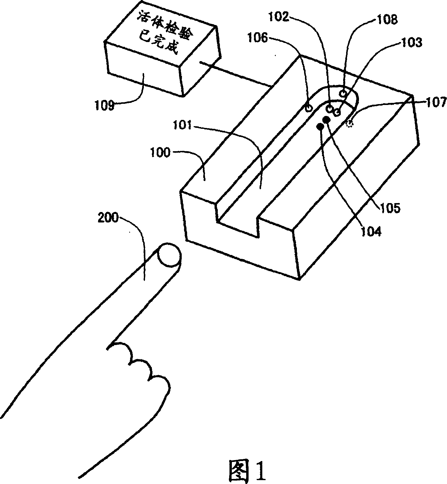
[0029] FIG. 1 is an external view of a biometric authentication device 100 according to an embodiment of the present invention. On the bottom surface of the finger placement part 101 where the finger 200 used for biometric authentication is placed, the optical axes of the light sources 102, 103 such as LEDs or lasers are arranged so as to be perpendicular to the bottom surface. The photosensitive surfaces of the portions 104 and 105 are arranged parallel to the bottom surface. In addition, light sources 106 , 107 , 108 such as LEDs or lasers are arranged on side surfaces intersecting at right angles to the bottom surface of finger rest 101 so that their optical axes are perpendicular to the side surfaces. The optical axes of the light sources 106 , 107 , 108 are perpendicular to the optical axes of the light sources 102 , 103 , and the photosensitive surfaces of the photosensitive parts 104 and 105 are parallel to the optical axes of the light sources 106 , 107 , 108 . In add...

Embodiment 2

[0036]FIG. 6 is an embodiment in which the biometric authentication device of the present invention is incorporated into biometric authentication based on fingerprint imaging. In biometric authentication device 120 , fingerprint imaging unit 130 is incorporated on the bottom surface of fingerprint placement unit 101 that does not interfere with light sources 102 , 103 , 106 , 107 , 108 and photoreceptors 104 , 105 . As an authentication method, first place a finger on the finger rest unit 101, and after the determination of the biopsy is performed, the finger is gently pressed against the bottom of the finger rest unit 101 while withdrawing it to the front, thereby obtaining a fingerprint in the fingerprint imaging unit 130. fingerprint image. In addition, in FIG. 6 , the biometric authentication device 120 and the display unit 109 are separated, but the display unit 109 and the biometric authentication device 120 may be integrated.

Embodiment 3

[0038] Fig. 7 is an embodiment of incorporating the biometric authentication device of the present invention into biometric authentication based on vein imaging. In biometric authentication device 140 , vein imaging unit 150 is incorporated in the bottom surface of finger rest unit 101 that does not interfere with light sources 102 , 103 , 106 , 107 , 108 and light receiving units 104 , 105 . In addition, as a light source for vein imaging, the imaging light source 110 is incorporated in a surface perpendicular to the surface of the vein imaging unit 150 . In the authentication method, at first, a finger is placed on the finger placement unit 101, and after the determination of the biopsy is carried out, the imaging light source 110 is made to emit light while the finger is placed on the finger placement unit 101, and the vein imaging unit 150 obtains the fingerprint of the finger. vein. In addition, in FIG. 7 , the biometric authentication device 140 and the display unit 109...


PUM


Abstract

A biometric identification apparatus that can accurately and rapidly perform liveness detection with a simple structure. [Solution] The apparatus includes a plurality of light sources 102, 103, 106 , and 107 , each having a wavelength different from one another, for emitting light to a finger 200 as an object to be identified, and receivers 104 and 105 for detecting the light passing through the finger. The ratio of the light emitted from the light sources to the light detected with the receivers is obtained as transmittance. Determination in liveness detection is made by comparing the transmittance with a previously-set threshold of transmittance.

Description

technical field [0001] The present invention relates to a living body authentication device. Background technique [0002] Biometric authentication technology based on personal biometrics (fingerprint, vein, iridescence, etc.) has received many proposals as a method of identity verification in bank ATMs, entry and exit of managed areas, computer login, and the like. [0003] The basic configuration of the biometric authentication device is to verify the person by registering the biometric information of the person to be authenticated in advance and checking the registered information. However, there is a fear of stealing the login information and creating an elaborate fake living body (fake finger, fake rainbow, etc.) based on the information to pretend to be the real person. [0004] Therefore, as a biometric authentication device for preventing counterfeiting, as described in Patent Documents 1 and 2, there is a method in which vein images are captured temporally consecut...

Claims


Application Information

Patent Timeline
Patent Type & Authority Applications(China)
IPC IPC(8): A61B5/117A61B5/00G06F15/00G06K9/00
CPCG06K2009/0006A61B5/1172G06K9/00912G06K9/0012A61B5/0059G06K2009/00932G06K9/00906G06V40/1341G06V40/1394G06V40/67G06V40/45G06V40/14
Inventor 横山真吾阿部忠幸菅生浩美佐藤正一
Owner HITACHI MEDIA ELECTORONICS CO LTD
Why Eureka
Try Eureka