Science instrument working state monitoring method based on computer vision

A computer vision and scientific instrument technology, applied in computer parts, instruments, computing, etc., can solve problems such as inability to view status indicators, no detailed working hours, status records, and inability to realize network monitoring.

Inactive Publication Date: 2008-02-13
JILIN UNIV
View PDF2 Cites 15 Cited by
  • Summary
  • Abstract
  • Description
  • Claims
  • Application Information

AI Technical Summary

Problems solved by technology

Such as Chinese patent CN 1308984C discloses a kind of invention indicating the working state of equipment, this method only provides the indication of working state, does not have detailed working time, state record, and can not realize networked monitoring; ) discloses a device for monitoring the working state of an instrument in the form of hardware, which collects working state information from the state indicating parts on the periphery of the instr...

Method used


Image

  • Science instrument working state monitoring method based on computer vision
  • Science instrument working state monitoring method based on computer vision
  • Science instrument working state monitoring method based on computer vision

Examples


Embodiment Construction

[0046] The specific implementation method will be described below by taking the working state monitoring of the EMX-SM7 electronic probe of Shimadzu Corporation of Japan as an example. 1. There are multiple status indicator lights on the panel of the electronic probe instrument. First, discuss with the instrument operator which status indicator light can scientifically reflect the vacuuming status of the instrument. This indicator light is defined as the status indicator light of interest.

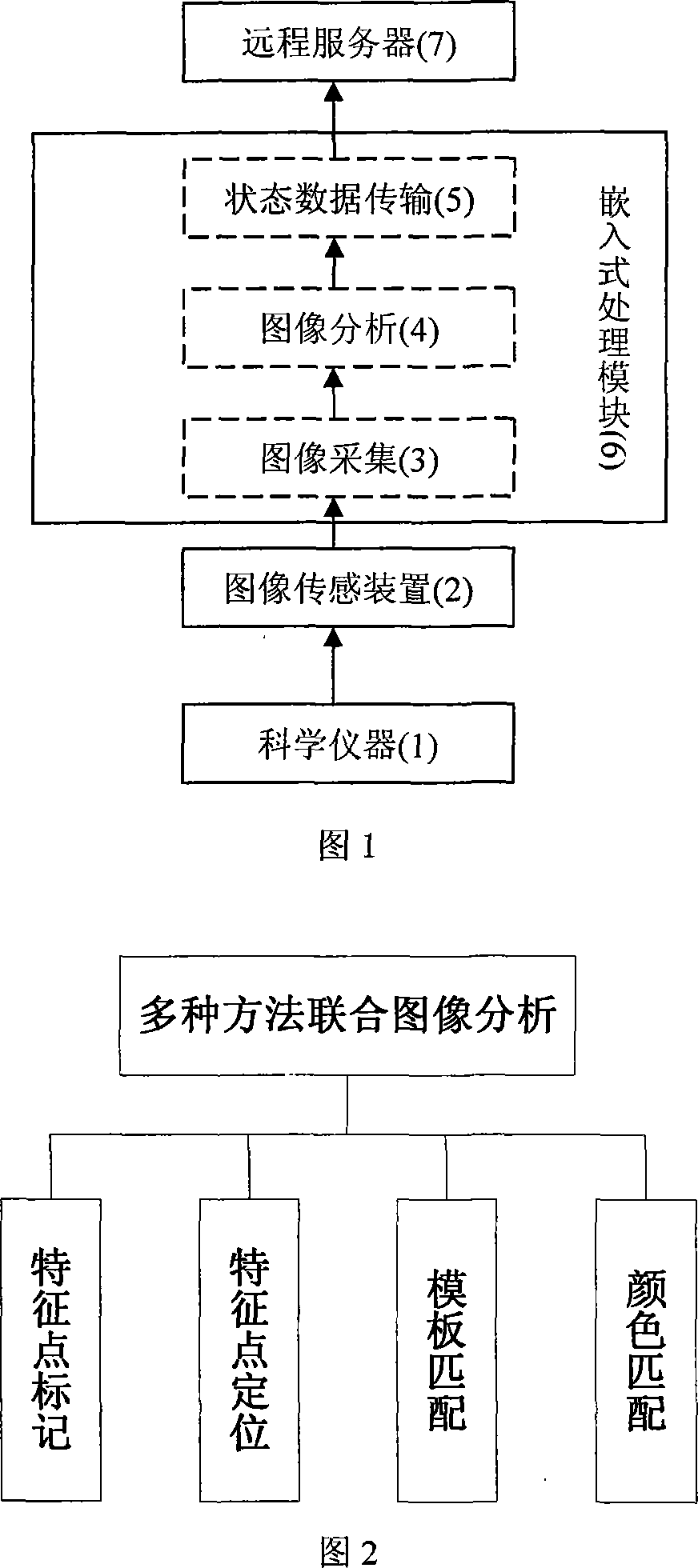
[0047]2. Align the image sensing device with the interested status indicator light, the image sensing device is connected with the embedded processing module, and the embedded processing module provides a network interface to connect to the Internet.

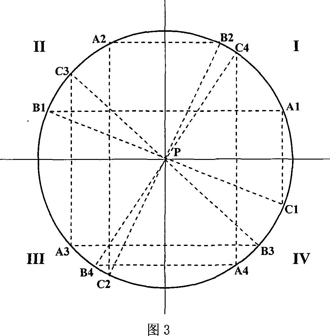
[0048] 3 Characterize the status indicator lights on the scientific instruments. Artificially draw a mark with a characteristic pattern under the status indicator light of interest, and intercept the images of the status indicator light bein...


PUM


Abstract

The invention relates to the field of computer application technologies, and discloses a scientific instrument working status monitoring method based on computer vision, which comprises an image collecting part, an image analyzing part and a status data transmission part. An image sensing device is used for transmitting the collected images of the scientific instrument working status indicator to the embedded processing module for image analysis and processing, acquiring working status of the instrument, and transmitting the working status to a remote server via the Internet. In the image analyzing process, a plurality of ways including characteristic point marking, characterized point positioning based on circle detection, template matching and color matching are jointly used for identifying working status of the instrument. The characterized point positioning is realized through the algorithm of circle detection based on an inscribed right-angle triangle. The circle detection algorithm establishes an array storage space based on effective pixel positions. The invention applies computer visual detection technologies to monitoring of scientific instruments, and realizes reliable and real-time remote monitoring of working status of scientific instruments.

Description

technical field [0001] The invention belongs to the technical field of computer applications, and relates to a method for monitoring the working state of a scientific instrument, in particular to a remote monitoring method for the working state of a scientific instrument based on computer vision. Background technique [0002] There are three main types of existing scientific instrument working state monitoring methods. [0003] One: Some scientific instruments have their own automatic recording of the working status of the excitation source switch, such as the MAT-251 stable isotope gas mass spectrometer from Thermo Finnigan, the JSM-6700F from JEOL, and so on. This type of method indicates the working status of the instrument through the information display of the code disc device and the control software, and only supports localized data viewing. The instrument itself does not provide a data network interface, and cannot realize networked real-time monitoring of the instru...

Claims


Application Information

Patent Timeline
IPC IPC(8): G06K9/00G06K9/62G06T7/00
Inventor 田地商飞邱春玲马骏骁龙涛王丰贵杨光李春生杨红生刘金伟乔艳明孙蕊
Owner JILIN UNIV
Why Eureka
Try Eureka