Hollow compound insulator for 1100kV combined electrical appliance and its making method

A technology of composite insulators and combined electrical appliances, applied in insulators, lead-in/through-type insulators, circuits, etc., can solve the problems of low yield of large-scale porcelain sleeves, easy damage to other equipment, complicated firing process, etc., and achieve reliable performance. , The effect of uniform laying and high connection strength

Active Publication Date: 2008-02-13
JIANGSU SHENMA ELECTRIC CO LTD
View PDF0 Cites 32 Cited by
  • Summary
  • Abstract
  • Description
  • Claims
  • Application Information

AI Technical Summary

Problems solved by technology

Porcelain sleeves are heavy, easy to damage other equipment after explosion, low po

Method used


Image

  • Hollow compound insulator for 1100kV combined electrical appliance and its making method
  • Hollow compound insulator for 1100kV combined electrical appliance and its making method

Examples


manufacture example 1

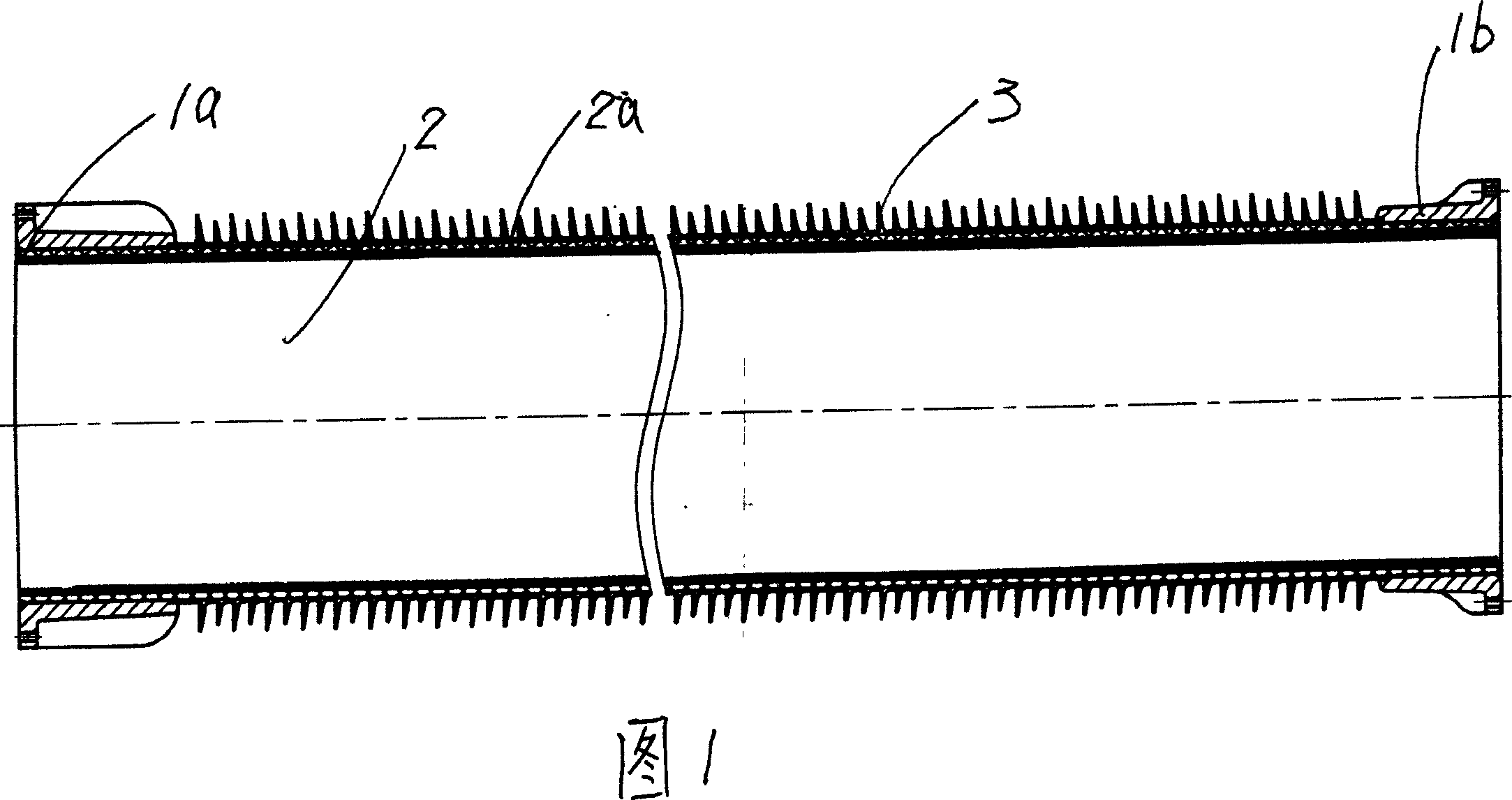
[0037] The umbrella body 3 is made of high-temperature vulcanized silicone rubber, and its components by weight are: 25% methyl vinyl silicone rubber, 35% white carbon black, 35% aluminum hydroxide, 4% silicone oil, and 1% vulcanizing agent.

[0038] Manufacturing steps:

[0039] ① On the mold core of the insulating tube 2 to be wound, fix pins at both ends of the axis of the simulated trajectory;

[0040] ②Apply epoxy resin glue and SF evenly on the mold core of the insulating tube 2 to be wound 6 A mixture of decomposed products to form the lining layer 2a;

[0041] ③ On the basis of step ②, the glass fiber yarn impregnated with epoxy resin glue is evenly wound on the mold core through a constant tension control mechanism to form a hollow tube body to a preset thickness;

[0042] ④ curing the hollow tube made in step ③ at high temperature;

[0043] ⑤ Machining the hollow tube made in step ④ to make the insulating tube 2;

[0044] ⑥Apply the coupling agent evenly on the o...

manufacture example 2

[0052] The umbrella body 3 is made of high-temperature vulcanized silicone rubber, and its components by weight are: 30% methyl vinyl silicone rubber, 33% white carbon black, 33% aluminum hydroxide, 3% silicone oil, and 1% vulcanizing agent.

[0053] Manufacturing steps:

[0054] ① On the mold core of the insulating tube 2 to be wound, fix pins at both ends of the axis of the simulated trajectory;

[0055] ②Apply epoxy resin glue and SF evenly on the mold core of the insulating tube 2 to be wound 6 A mixture of decomposed products to form the lining layer 2a;

[0056] ③ On the basis of step ②, the glass fiber yarn impregnated with epoxy resin glue is evenly wound on the mold core through a constant tension control mechanism to form a hollow tube body to a preset thickness;

[0057] ④ curing the hollow tube made in step ③ at high temperature;

[0058] ⑤ Machining the hollow tube made in step ④ to make the insulating tube 2;

[0059]⑥Apply the coupling agent evenly on the ou...


PUM


Abstract

The invention relates to a hollow composite insulator used in 1100kV composite apparatus in power industry, and a producing method of the insulator. The insulator comprises an end connecting part, an insulation tube and an umbrella. The end connecting parts are stuck on the two ends of the winding tube. The invention is characterized in that: an integrated umbrella is stuck at the out side of an insulation tube; the insulation tube is a wound tube with an inner liner; the umbrella is an injecting-formed part made of high-temperature vulcanization silicon rubber, and because the inner liner of the insulation tube is an epoxy resin adhesive and SF6 decomposition mixing and solidifying structure, the anti-corrosion performance of the product is greatly increased; the umbrella is hot-solidified on the surface of the insulation tube at high vacuum and high temperature, so the connecting strength between the umbrella and the insulation tube is high, and the product performance is more stable and reliable. When winding the insulation tube, a track is first simulated on a computer, and then pins are fixed on both shaft ends of the mold core. When winding, a tension mechanism with even and constant tensile force is used for control, thus realizing even paving of the glass fiber.

Description

technical field [0001] The invention relates to a hollow composite insulator for high-voltage power transmission and transformation in the power industry, in particular to a hollow composite insulator for 1100kV combined electrical appliances and a manufacturing method thereof. Background technique [0002] After retrieving the relevant patent documents, the hollow composite insulator and its manufacturing method for 1100kV combined electrical appliances with the same structure as the present invention have not yet been retrieved. The existing power transmission and transformation insulators are mainly divided into two categories: porcelain sleeves made of porcelain materials and silicone rubber hollow composite insulators. The weight of the porcelain sleeve is heavy, and it is easy to damage other equipment after an explosion. The pollution resistance is low, the firing process is complicated, and the yield of large porcelain sleeves is low. Due to the high requirements fo...

Claims


Application Information

Patent Timeline
IPC IPC(8): H01B17/00H01B17/26H01B19/00
Inventor 马斌
Owner JIANGSU SHENMA ELECTRIC CO LTD
Why Eureka
Try Eureka