Column-shape magnetron sputtering equipment

A sputter and columnar technology is applied in the field of magnetron sputtering, which can solve the problems of affecting the utilization rate of cylindrical magnetron sputtering equipment, unable to ensure long-term stable operation of the sputter, and restricting the application of cylindrical magnetron sputtering, etc. Achieve the effect of weakening the end effect, easy installation and general use, and convenient magnetic field arrangement

Active Publication Date: 2008-02-20
深圳豪威显示科技有限公司
View PDF1 Cites 11 Cited by
  • Summary
  • Abstract
  • Description
  • Claims
  • Application Information

AI Technical Summary

Problems solved by technology

[0008] ① The end of the cylindrical target will have a deeper score than the middle section, which is the main reason for the further improvement of the utilization rate of the cylindrical magnetron sputtering equipment;
[0009] ②Cylindrical magnetron sputtering involves the problem of dynamic sealing. The commonly used magnetron sputtering targets now use sealing rings for dynamic sealing, which obviously cannot guarantee the long-term stable operation of the sputtering device;
[0010] ③The installation method is single, and the commonly used cylindrical magnetron sputtering devices are all installed on the top of the sputtering studio
The application of cylindrical magnetron sputtering is limited, so the overall structure needs to be changed;
[0011] ④ Ordinary cylindrical magnetron sputtering is usually used to load power in DC mode, which limits its application field

Method used


Image

  • Column-shape magnetron sputtering equipment
  • Column-shape magnetron sputtering equipment
  • Column-shape magnetron sputtering equipment

Examples


Embodiment Construction

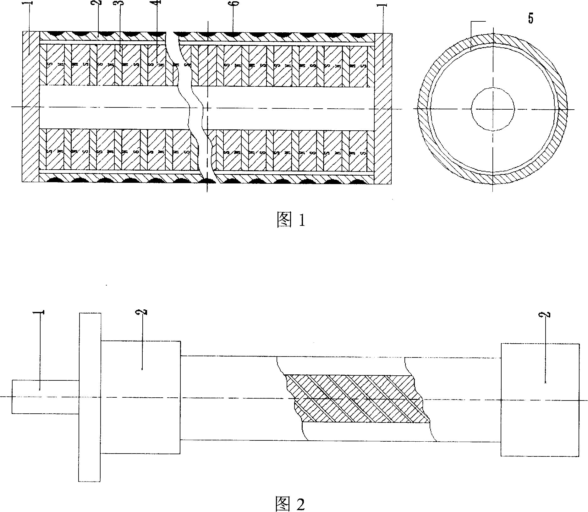
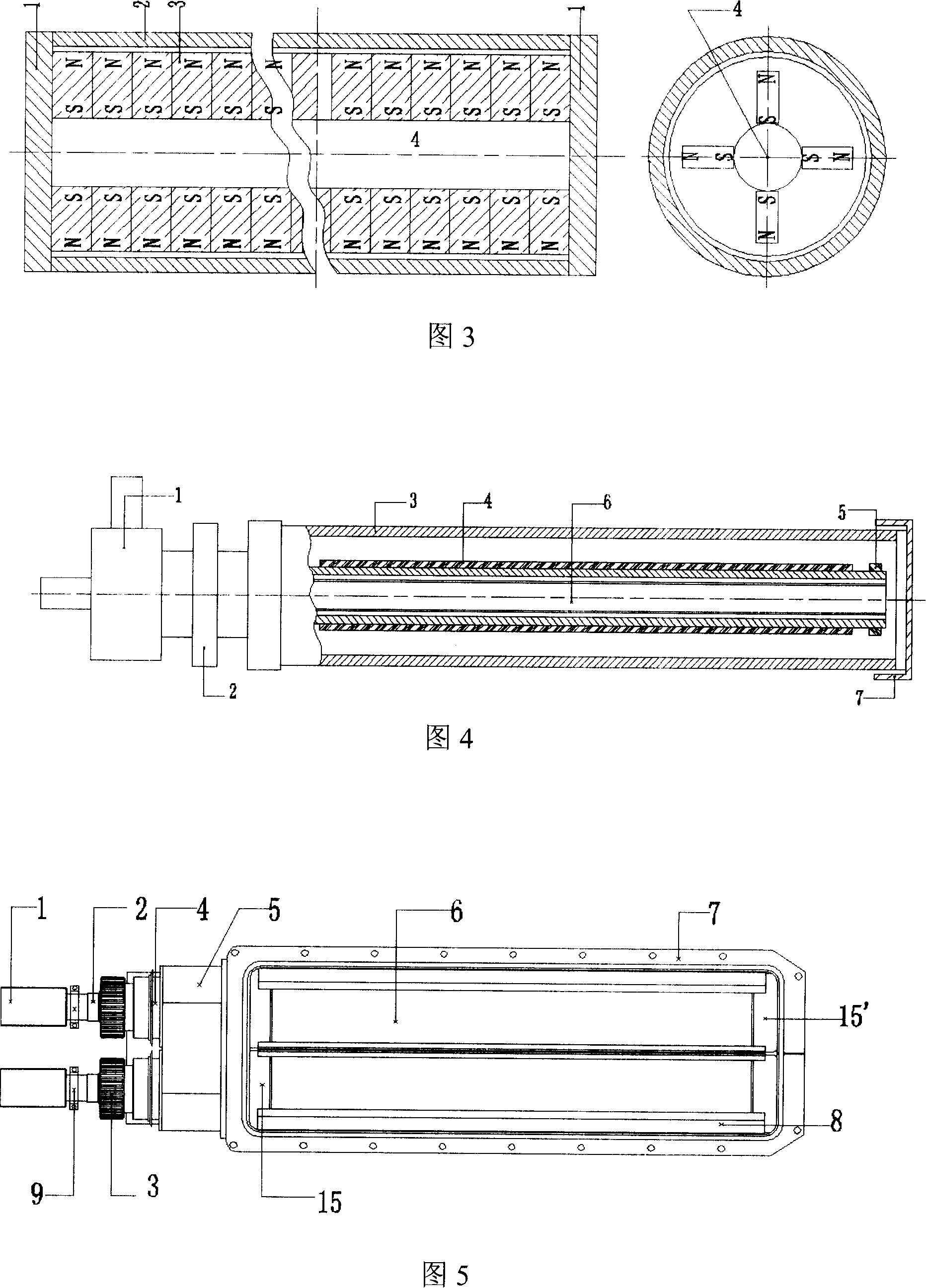
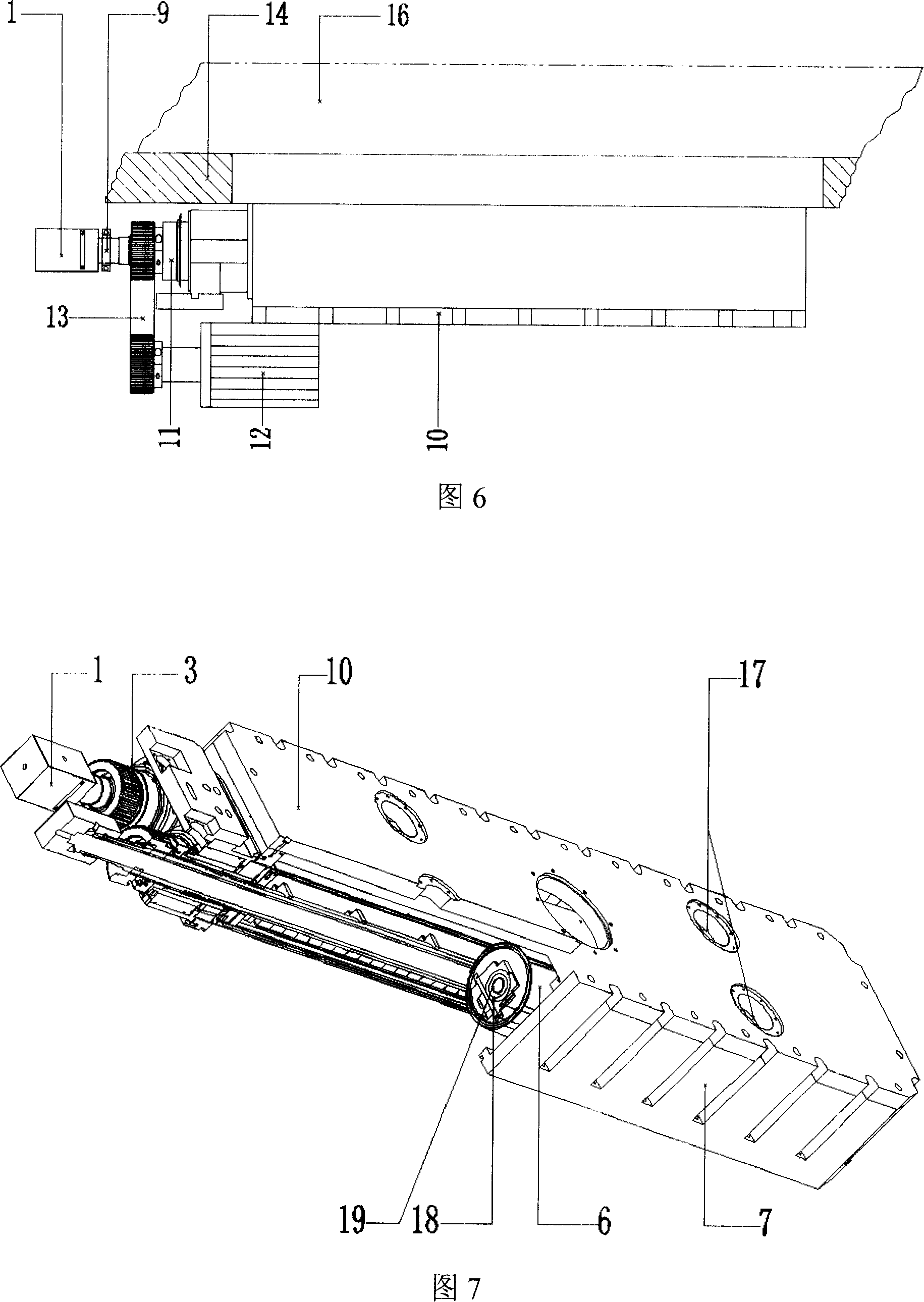
[0043] A closed columnar magnetron sputtering device, see Fig. 5-Fig. 13, includes a rotating water base 1, a rotating shaft 2, a synchronous wheel 3, a magnetic fluid device 4, a sputtering rotating base 5, a target cylinder (with a tubular target Material) 6, sputter base 7, shielding cover 8, spindle clamp 9, rear sealing plate 10, brush ring 11, frequency conversion motor 12, timing belt 13, sputter mounting seat 14, magnetic pole device 20, cooling Water conduit 19, gas distribution introduction hole 17, sputtering working chamber 15, main shaft 18 and upper and lower sealing end caps (15, 15') of the target cylinder.

[0044]Referring to Fig. 5-Fig. 8, a pair of target cylinder 6 and magnetic pole arrangement 20 (seeing Fig. 7 and Fig. 8) with tubular target material are installed in the sputter base 7, and the target cylinder 6 facing away from the magnetic pole arrangement 20 Shielding cover 8 is installed on the side. The synchronous wheel 3 and the rotating shaft 2 ...


PUM


Abstract

The invention discloses a pole-shaped device of magnetron sputtering, comprising a target barrel, an arc shelter cap and a magnetic pole device; the arc shelter cap is arranged at the side face of the target barrel; the magnetic pole device consists of a plate type field yoke, a side magnet steel and a central magnet steel which are fixed parallel on the plate type field yoke and parallel with the plane and a central separating strip is positioned between the side magnet steel and the central magnet steel; the plate type filed yoke is fixed parallel at the other side face of target barrel opposite to the arc shelter cap. Furthermore, strengthening magnet steels are mounted at the upper and the lower end faces of the central magnet steel, the height of the end face of strengthening magnet steel which closes to the end face of the central magnet steel is lower than that of the end face of the central magnet steel. Due to the strengthening magnet steel, the invention overcomes the disadvantages that the arrangement of the prior magnet poles can cause the magnetic field of end face is weaker than that of central magnetic field, so as to ensure a much even level magnetic field of target face; thus, the whole mechanical erosion of the target is even and the magnetic circuit is completely closed, further increasing the utility rate of the target.

Description

technical field [0001] The invention relates to a magnetron sputtering technology, which can be applied to a production line or a single device to prepare thin films by a DC or intermediate frequency method. Metal film and dielectric film can be prepared, especially suitable for sputtering of expensive targets. Background technique [0002] Compared with traditional evaporation and chemical deposition thin films, magnetron sputtering technology has ① excellent film uniformity; ② film and substrate are firmly bonded; ③ can improve the properties of film by changing the corresponding parameters and mechanical mechanism; ④ The advantages of being less affected by the properties of the substrate have been the most widely used. In the production process, considering the production cost and production efficiency, the utilization rate of the target material has not been greatly improved in the traditional cylindrical magnetron sputtering machine, and compared with the planar magne...

Claims


Application Information

Patent Timeline
Patent Type & Authority Applications(China)
IPC IPC(8): C23C14/35
Inventor 许生徐升东谭晓华
Owner 深圳豪威显示科技有限公司
Why Eureka
Try Eureka