High-sensitivity resonance type optical fiber peg-top based on slow light group velocity

A high-sensitivity, fiber optic gyroscope technology, applied in the coupling of optical waveguides, Sagnac effect gyroscopes, optics, etc., can solve the problems of low sensitivity, unable to meet the attitude alignment of missiles and commercial aircraft, and achieve small size, The effect of low cost and simple structure

Inactive Publication Date: 2008-02-20
HARBIN INST OF TECH
View PDF0 Cites 13 Cited by
  • Summary
  • Abstract
  • Description
  • Claims
  • Application Information

AI Technical Summary

Problems solved by technology

[0003] The present invention aims to overcome the low sensitivity (0.1 degree / hour) of the existing resonant fiber optic gyroscope, which cannot meet the attitude alignment of short-range / medium-range missiles and commercial aircraft, especially in terms of space positioning and submarine navigation. For the problem of places with high sensitivity requirements, a high-sensitivity resonant fiber optic gyroscope based on slow light group velocity is proposed

Method used


Image

  • High-sensitivity resonance type optical fiber peg-top based on slow light group velocity
  • High-sensitivity resonance type optical fiber peg-top based on slow light group velocity

Examples


specific Embodiment approach 1

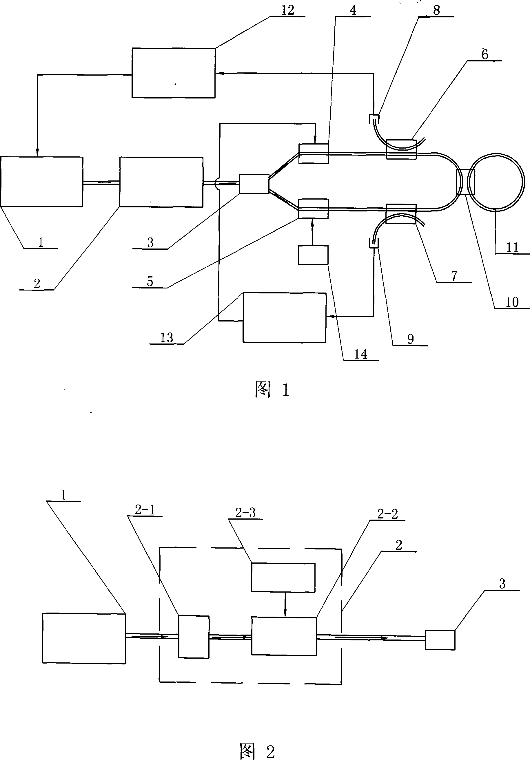
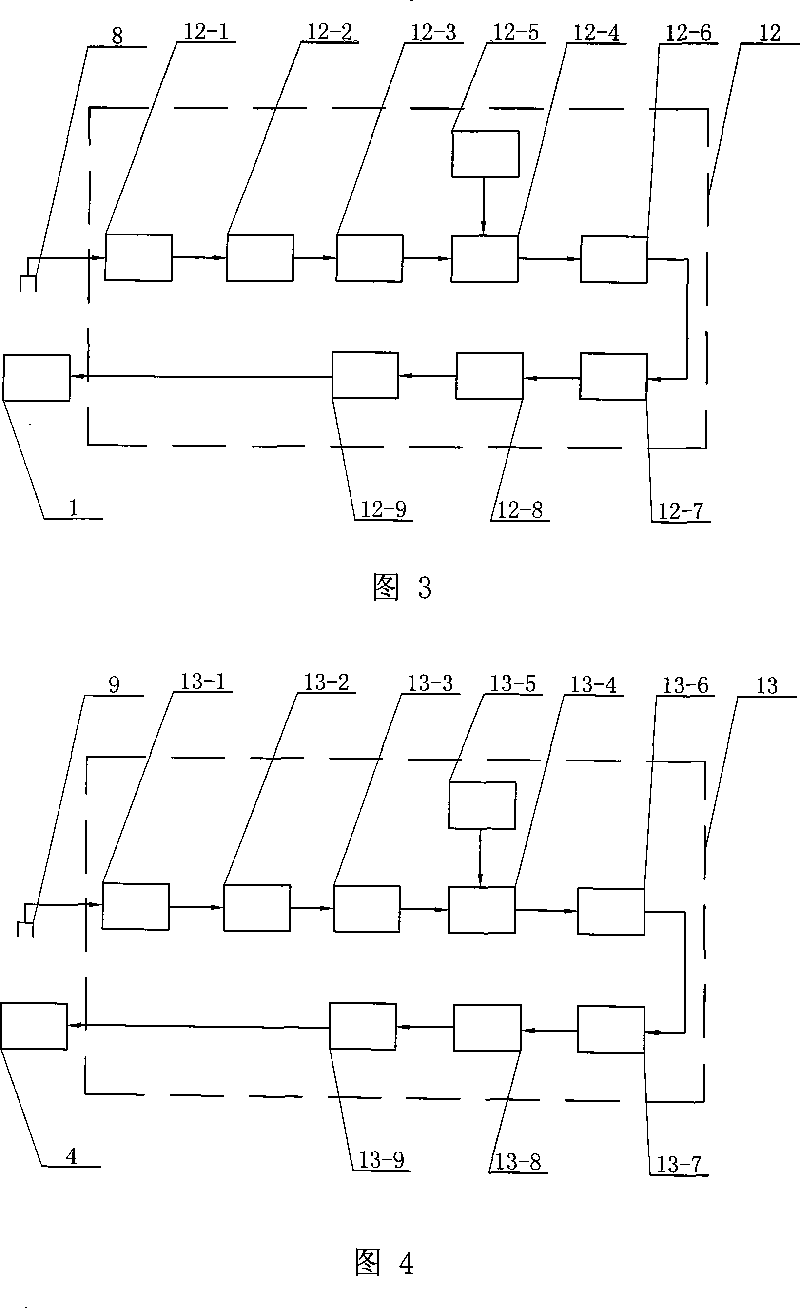
[0008] Specific Embodiment 1: This embodiment is described in conjunction with Fig. 1, Fig. 2, Fig. 3, and Fig. 4. This embodiment consists of a frequency conversion laser 1, a group velocity control system 2, an optical fiber beam splitter 3, and a first lithium niobate phase modulator 4. The second lithium niobate phase modulator 5, the first fiber coupler 6, the second fiber coupler 7, the first detector 8, the second detector 9, the third fiber coupler 10, the dispersion fiber ring resonator 11. The first signal processing and feedback system 12, the second signal processing and feedback system 13, and the modulation signal generating circuit 14;

[0009] The dispersion fiber ring resonator 11 is a hollow coil wound by a dispersion fiber; the laser output end of the frequency conversion laser 1 is connected to the optical input end of the group velocity control system 2 through an optical fiber, and the optical output end of the group velocity control system 2 is connected ...


PUM

PropertyMeasurementUnit
diameteraaaaaaaaaa

Abstract

The utility model relates to a resonator fiber optic gyro with high sensitivity, belonging to the technical field of a fiber optic gyro, which aims at overcoming the problems that low sensibility (0.1 degree / hour) exists upon prior resonator fiber optic gyro and can not meet attitude tracking of short range / midrange missiles and commercial aircrafts, more particularly can not meet areas such as space positioning and submarine navigation with high requirement for sensibility. The utility model is characterized in that a laser output end of a frequency conversion laser (1) is connected with a dispersion fiber ring resonator (11) through a group speed control system (2), a fiber beam splitter (3), a first lithium niobate phase modulator (4), a second lithium niobate phase modulator (5), a first optical fiber coupler (6), a second optical fiber coupler (7) and a third optical fiber coupler (10). The utility model has the advantages of high sensibility up to ng times (The ng is group speed refractive index), low production cost, simple structure and small size.

Description

technical field [0001] The invention relates to the technical field of fiber optic gyroscopes. Background technique [0002] In 1976, Vali and R.W.Shorthill of Utah University in the United States successfully developed the first fiber optic gyroscope. As soon as the fiber optic gyroscope came out, it attracted many universities and research institutes in the world with its obvious advantages, flexible structure and attractive prospects. The general attention of institutions has made great progress in the past few decades. The fiber ring resonators in the current resonant fiber optic gyroscope are made of low-loss common fiber material (high-purity silica). The number of fiber turns in the fiber ring cavity is about 12 turns, and the radius is 10-20cm. The rotation speed is determined by detecting the frequency difference at the output terminal, and the sensitivity of the gyroscope is limited. At present, the sensitivity of the laboratory is 0.1 degrees / hour, and it is diff...

Claims


Application Information

Patent Timeline
Patent Type & Authority Applications(China)
IPC IPC(8): G01C19/72G02B6/42G02B6/26G02F1/03
Inventor 掌蕴东田赫王楠袁萍
Owner HARBIN INST OF TECH
Why Eureka
Try Eureka