Eureka AIR delivers breakthrough ideas for toughest innovation challenges, trusted by R&D personnel around the world.

Phase separator

A technology of phase separators and branch pipelines, applied in separation methods, chemical instruments and methods, sampling devices, etc., can solve problems such as complex internal structures, affecting the accuracy of sampling and measurement, and difficult processing

Active Publication Date: 2008-02-20
NUCLEAR POWER INSTITUTE OF CHINA
View PDF0 Cites 12 Cited by
  • Summary
  • Abstract
  • Description
  • Claims
  • Application Information

AI Technical Summary

Problems solved by technology

However, the product separators such as the phase separator produced by the French ELTA company are all located above the sampling-separator. Before the vacuum separation, the gas sampling bottle has been connected with the separator, and the gas sampling bottle and the separator jointly participate in the bubbling process. In order to prevent sampling in the vacuum separation of water samples - the water samples in the separator enter the separator and affect the accuracy of sampling measurement. Sufficient, its primary segregation rate is only about 60%, and secondary segregation is required
In addition, such as the phase separator produced by the French ELTA company, its internal structure is very complicated, and it is difficult to process.
[0004] When the existing phase separator is used in nuclear power plants to measure the dissolved hydrogen content in water, due to the need for secondary segregation, the staff take a long time to take samples, receive high radioactive doses, and work efficiency is low

Method used


Image

  • Phase separator
  • Phase separator
  • Phase separator

Examples


Embodiment Construction

[0018] The phase separator of the present invention will be further described below in conjunction with the accompanying drawings.

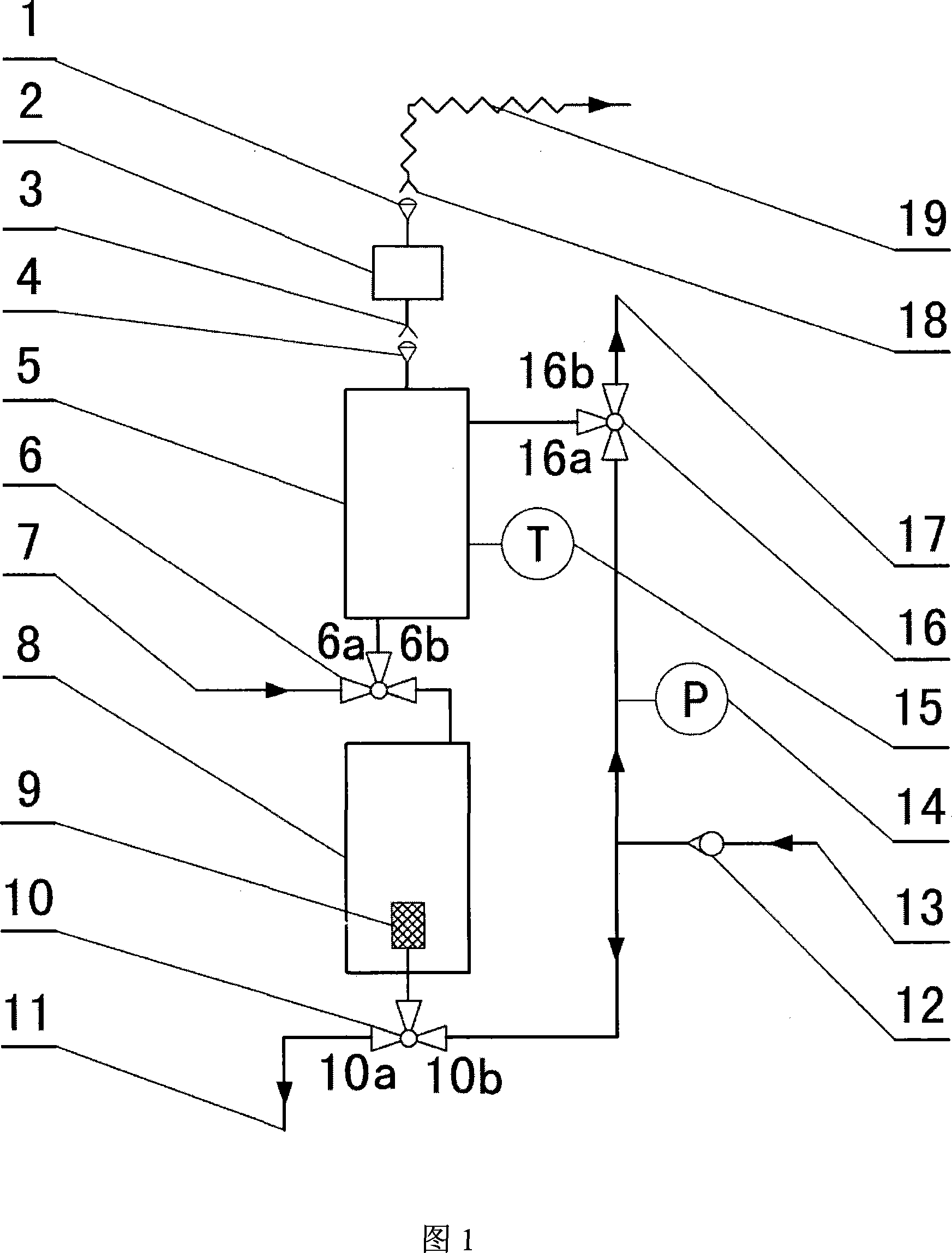
[0019] The phase separator of the present invention comprises a sampling unit, a vacuum line for evacuating the sampling unit and a bubbling line for feeding nitrogen (or inert gas) into the sampling unit.

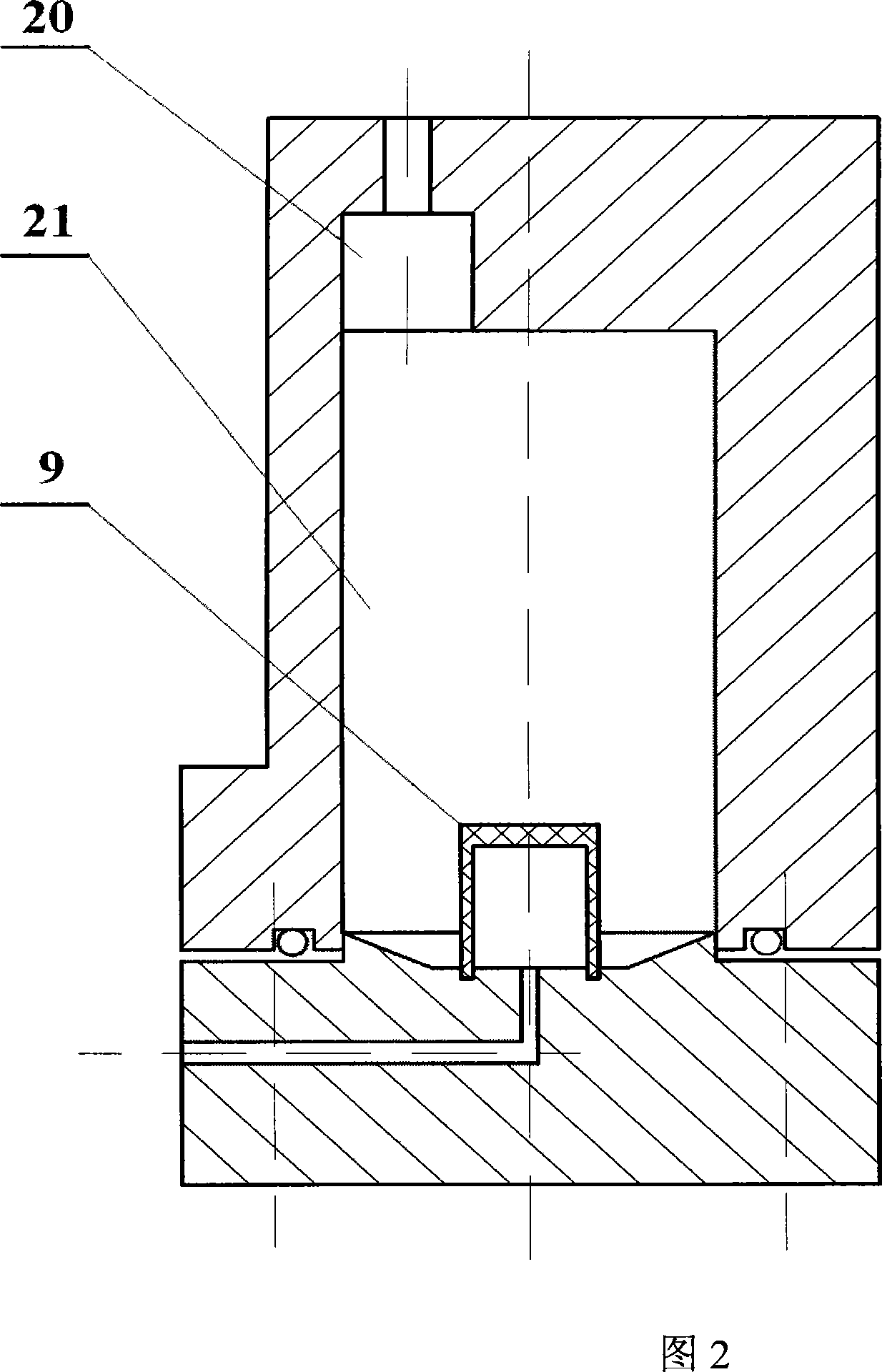
[0020] As shown in Figure 1, sampling unit comprises sampling-separator 5, the separator 8 that is provided with below sampling-separator 5, the gas sampling bottle 2 that is provided with above sampling-separator 5, in sampling-separator 5 A thermometer 15 that can directly read data is provided on the top. As shown in Figure 2, the inside of the separator 8 is divided into upper and lower cavities, the upper cavity 20 is an eccentric structure, and the center of the lower cavity 21 is provided with a bubbling element 9, and the volume of the lower cavity is the same as that of the sampling-separator 5. The same volume (or no more than 110%...


PUM


Abstract

The utility model relates to a phase separator, comprising a sampling element, a vacuum pipeline used to vacuumize the sampling element and a blister pipeline used to input nitrogen or inert gas into the sampling element; wherein, the sampling element is composed of a sampling-separator; a separator which can be connected or disconnected with the sampling-separator is arranged under the sampling-separator, and a gas sampling bottle which can be connected or disconnected with the sampling-separator is arranged above the sampling-separator. The interior of the separator is divided into two hollow cavities: an upper hollow cavity and a lower hollow cavity; wherein, the upper hollow cavity is an eccentric structure and the volume of the lower hollow cavity is 100 to 110 percent of the volume of the sampling-separator; a blister element is arranged in the middle of the lower hollow cavity of the separator. The phase separator of the utility model has the advantages of not needing secondary separation, having fast and convenient sampling, simple structure and easy maintenance, and high separation efficiency.

Description

technical field [0001] The invention relates to a separation device, in particular to a gas-liquid separation device capable of separating dissolved gas in water and used to obtain the content of dissolved gas in water. Background technique [0002] The measurement of dissolved gas content in water is mainly obtained through the following two methods: one is to use online dissolved gas analyzers (such as online dissolved hydrogen analyzers, online dissolved oxygen analyzers, etc.) to monitor the dissolved gases in water; the other is to use manual sampling The method is to separate the gas dissolved in water and send it to the laboratory for gas chromatography analysis, so as to obtain the content of dissolved gas in the collected water sample. The key to the second method is the manual sampling device. [0003] At present, the manual sampling device, such as the phase separator produced by the French ELTA company, works in accordance with Henry's law (Henry's law is that u...

Claims


Application Information

Patent Timeline
IPC IPC(8): G01N1/22G01N1/28B01D19/00
Inventor 王争光邱添李勇
Owner NUCLEAR POWER INSTITUTE OF CHINA
Why Eureka
Eureka Blog
Learn More