Anodising aluminium alloy

An anodizing and aluminum alloy technology, applied in anodic oxidation, electrolytic coating, surface reaction electrolytic coating, etc., can solve problems such as not suitable for bonding, and achieve the effect of superior peel strength

Active Publication Date: 2008-02-20
SHORT BROTHERS
View PDF1 Cites 9 Cited by
  • Summary
  • Abstract
  • Description
  • Claims
  • Application Information

AI Technical Summary

Problems solved by technology

This makes the process unsuitable for bonding

Method used


Image

  • Anodising aluminium alloy
  • Anodising aluminium alloy
  • Anodising aluminium alloy

Examples


Embodiment Construction

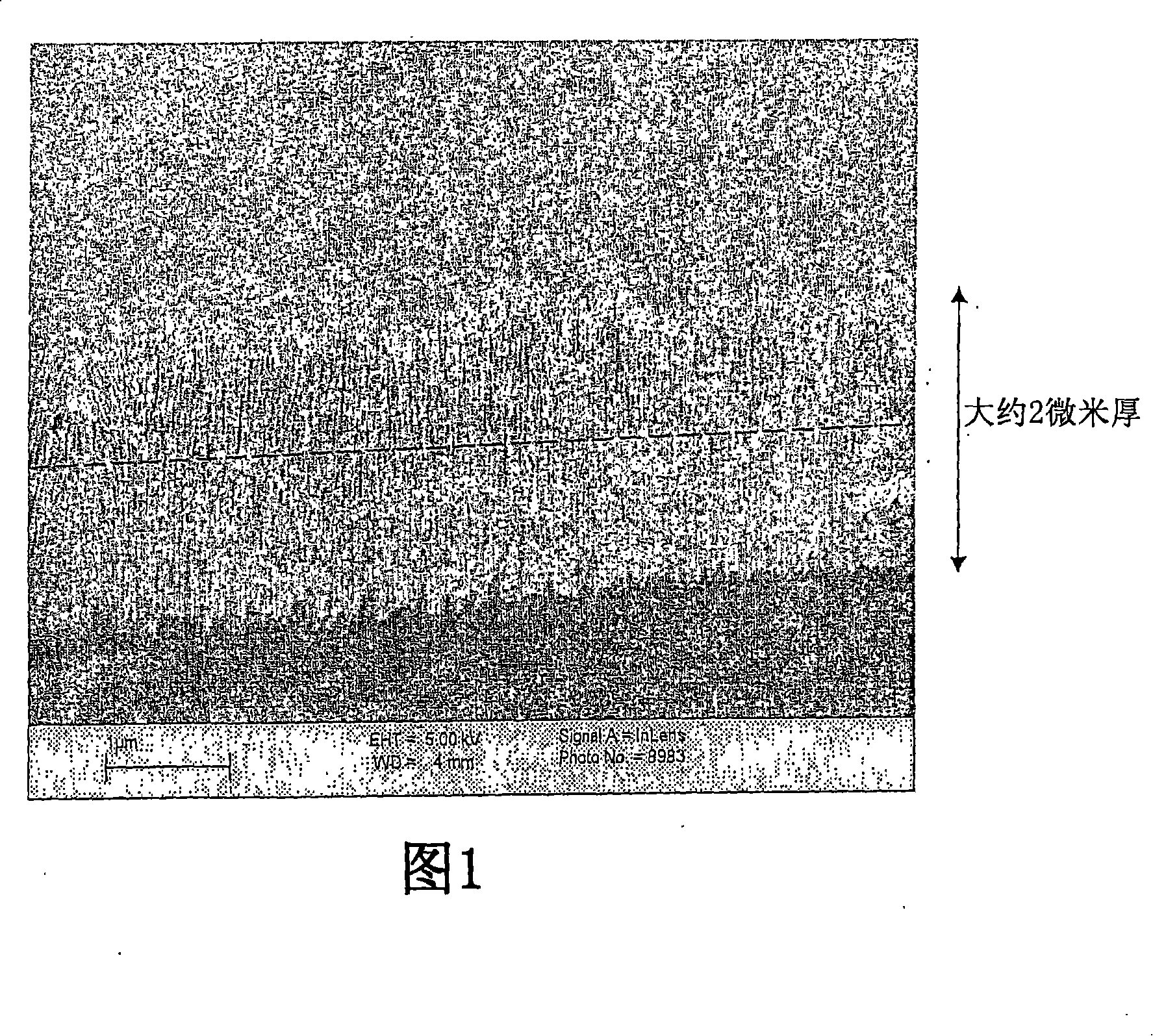
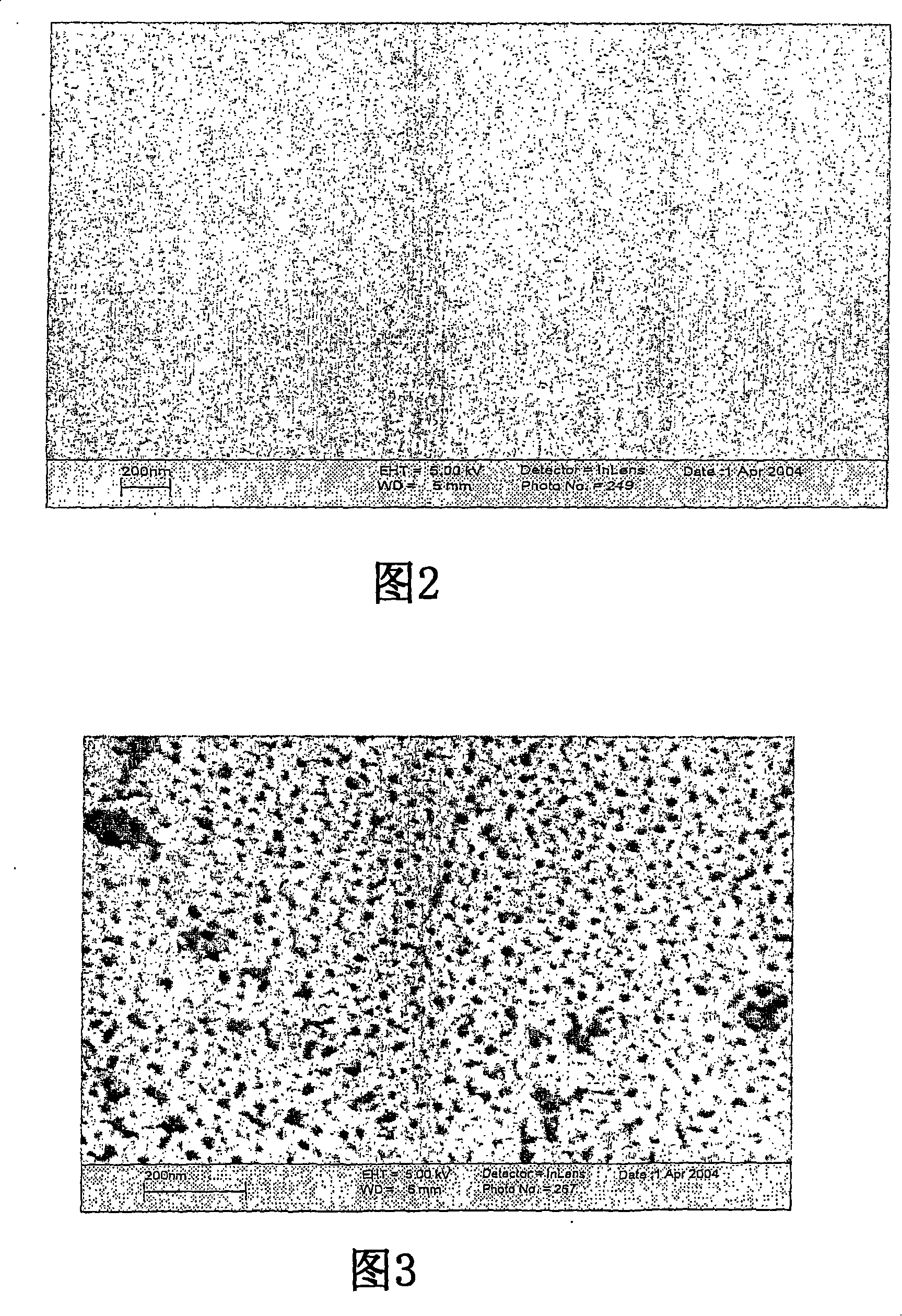
[0038] A bare 2024 aluminum alloy workpiece was connected to the anode of an anodized cell having a series of cathodes along the cell walls. No degreasing or deoxidizing treatment is applied to the workpiece prior to anodizing. The anodizing solution contained 2.5% sulfuric acid and 2.5% phosphoric acid. The cell was maintained at a temperature of 35°C. The workpiece was anodized for 120 seconds using a single phase AC current of 50 Hz, 15 volts. Immediately thereafter, DC anodization was performed in the same cell for 600 seconds with a DC current of 20 volts. After anodizing, wash the workpiece in water to remove traces of the anodizing solution. Examination of the resulting anodized film revealed a film with a dual structure in which the thickness of the outer layer was about 0.5 microns and the diameter of the pores was about 30 nanometers. The thickness of the inner layer is about 1.5 microns, which is substantially non-porous, as shown in FIG. 1 .

[0039] Especiall...


PUM

PropertyMeasurementUnit
thicknessaaaaaaaaaa
thicknessaaaaaaaaaa
thicknessaaaaaaaaaa

Abstract

An anodic oxide film is formed on an aluminium or aluminium alloy work piece by forming an anodic oxide film on the work piece by AC electrolysis followed by subjecting the work piece to DC electrolysis. The AC anodising step may be conducted at a voltage of 5 to 30V for 30 seconds to 10 minutes and the DC anodising step may be conducted at a voltage of 5 to 30V for a period of 1 to 20 minutes. The anodic oxide coating is suitable for adhesive bonding of aluminium alloy work pieces.

Description

technical field [0001] The present invention relates to the formation of anodized films on aluminum or aluminum alloys, which are of particular but not exclusive benefit to the aerospace and automotive industries, wherein the aluminum alloys (typically 2000, 5000, 6000 and 7000 series aluminum alloys) utilize anodic Aluminum oxide or aluminum hydroxide coating. More specifically, the process provides an anodized layer suitable for bonding aluminum alloy workpieces. Background technique [0002] In the aerospace and automotive industries, as well as in other similar industries, aluminum alloy structures are anodized for two main reasons. First, an aluminum oxide layer or aluminum hydroxide layer (hereinafter referred to as anodized film) is formed on the surface of the component to provide an impermeable barrier to prevent the component from being corroded by the atmosphere. Second, a layer is formed on the surface of the part to serve as a bonding surface for areas of orga...

Claims


Application Information

Patent Timeline
Patent Type & Authority Applications(China)
IPC IPC(8): C25D11/12C25D1/04C25D5/18
CPCC25D11/08C25D11/12Y10T428/12479C25D11/00C25D11/02C25D11/04C25D21/12
Inventor 加里·克里奇洛扬·阿什克罗夫特蒂莫西·卡特赖特戴维·巴拉尼
Owner SHORT BROTHERS
Why Eureka
Try Eureka