High-speed movable bearing in particular for the mounting of a main spindle of a machine tool

A floating bearing, high-speed technology, applied in the direction of rolling contact bearings, ball bearings, shafts and bearings, can solve the problems of material damage, low load capacity, complete failure, etc.

Inactive Publication Date: 2008-02-27
SCHAEFFLER KG
View PDF1 Cites 11 Cited by
  • Summary
  • Abstract
  • Description
  • Claims
  • Application Information

AI Technical Summary

Problems solved by technology

[0005] Although a ball bearing of this type overcomes the radial thermal expansion of the bearing ring due to operation through its defined radial play, it has the disadvantage that it has only a low load-carrying capacity and is therefore less susceptible to so-called crash accidents. , where the bearing is suddenly subjected to very high point loads, prone to material damage and eventually to outright failure
It has been proven in practice that even the specified radial clearance of the bearing is still not sufficient to avoid overloading of the bearing in the event of a large heat drop from the inner bearing ring to the outer bearing ring, so that with such bearings even in a two-row configuration It is not possible to ensure regular and precise radial spindle guidance in any operating state of the bearing

Method used


Image

  • High-speed movable bearing in particular for the mounting of a main spindle of a machine tool
  • High-speed movable bearing in particular for the mounting of a main spindle of a machine tool

Examples


Embodiment Construction

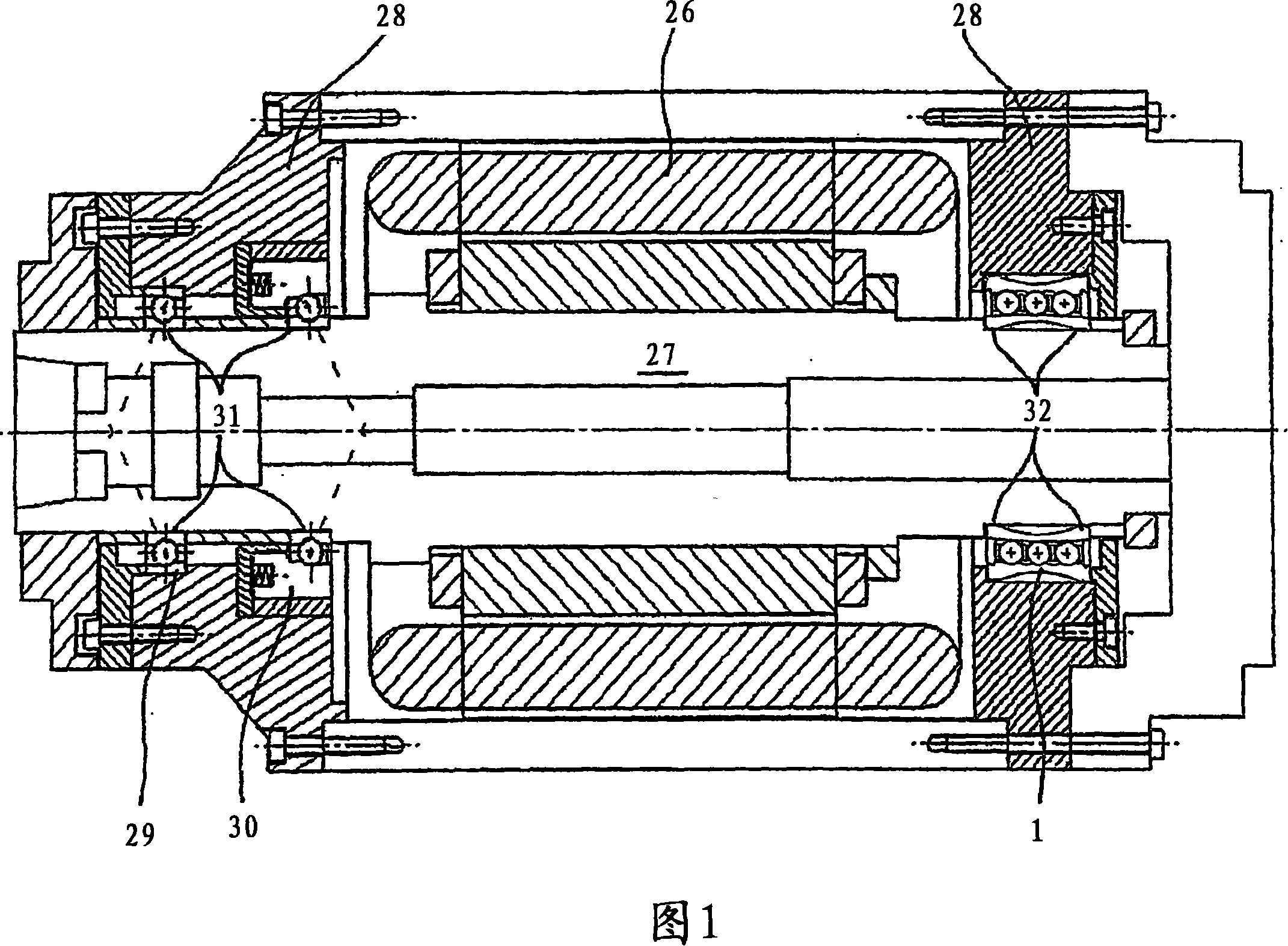
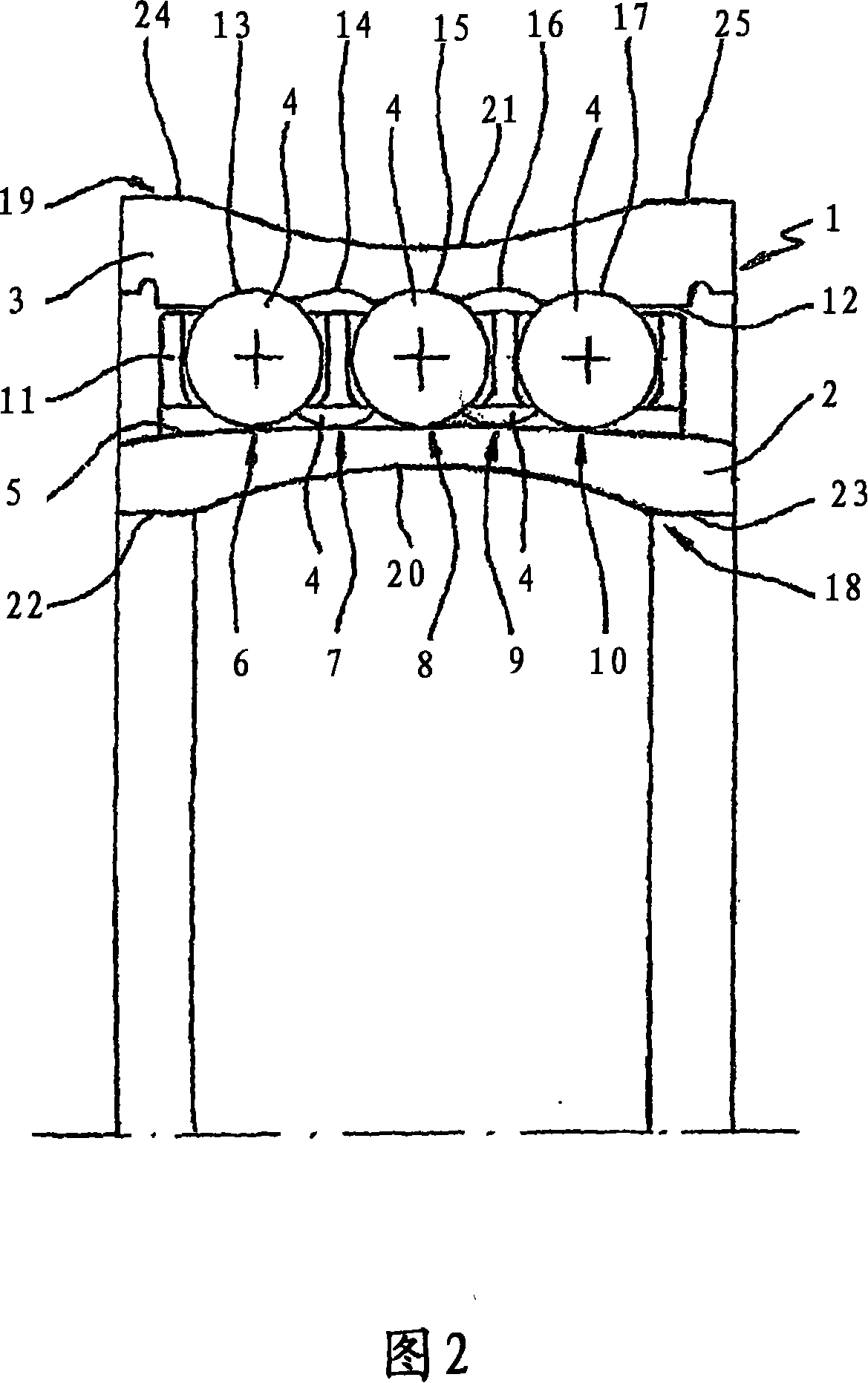
[0017]FIG. 1 shows schematically a drive for a processing machine tool, which essentially comprises an electric motor 26 and a spindle 27 driven by the motor. The main shaft 27 is visibly mounted at one end in two angular contact ball bearings 29 , 30 which are formed as fixed bearing seats 31 in the main shaft housing 28 . The other end of the main shaft 10 is supported in a floating bearing seat 32 which is formed by the high-speed floating bearing 1 according to the invention. For this reason, it can be seen from FIG. 2 that the high-speed floating bearing 1 basically includes an inner bearing ring 2 fixed on the main shaft 27, an outer bearing ring 3 fixed in the main shaft housing 28, and some bearing rings 2 arranged on the bearing ring 2. , 3 between the rolling elements 4 and has the possibility to function as a floating bearing, that is, the axial movement of the inner bearing ring 2 in the area of ​​its rolling surface 5 for the rolling elements 4 .

[0018] Further...


PUM


Abstract

According to the invention, the high-speed moving bearing (1) is embodied as an automatically-compensating movable ball bearing with several adjacent races of balls (6, 7, 8, 9, 10) with operation-dependent radial thermal expansion of the bearing rings (2, 3), the bearing rings (2, 3) of which are only in supporting contact with one ball race (8) in the cold state for the high-speed movable bearing (1), by means of a convex embodiment of the running surfaces (5) for the roller bodies (4) on the inner bearing ring (2). With increasing thermal expansion and expansion due to centrifugal force of both bearing rings (2, 3), the further ball races (6, 7, 9, 10) come sequentially into such a contact position with both bearing rings (2, 3) as a result of an elastic radially-flexible embodiment of both bearing rings (2, 3), that the bearing rings (2, 3) at the operating temperature for the high-speed moving bearing (1) are in supporting contact with all ball races (6, 7, 8, 9, 10).

Description

technical field [0001] The invention relates to a high-speed floating bearing according to the preamble of claim 1 , which can be used particularly advantageously for supporting machine tool spindles or for supporting other rapidly rotating machine components. Background technique [0002] It is generally known to those skilled in the field of rolling bearing technology that at least two bearings arranged at a predetermined distance from one another are required for guiding and supporting rotating machine components. If the shaft is usually supported in two radial bearings, the problem arises that the distances of the individual bearing seats on the shaft and in the housing only match within the limits of manufacturing tolerances. Furthermore, the shaft generally heats up more than the housing under operating conditions, so temperature-induced length differences of the shaft at the bearing point must also be compensated. It has long been possible to effectively compensate f...

Claims


Application Information

Patent Timeline
Patent Type & Authority Applications(China)
IPC IPC(8): F16C19/08F16C27/04
CPCF16C19/08F16C33/58F16C27/04F16C2322/39Y10T409/309352
Inventor W·阿尔贝特
Owner SCHAEFFLER KG
Why Eureka
Try Eureka