

Elastic bearing plate
A technology of elastic backing plate and elastic layer, which is applied in the directions of roads, tracks, ballast layers, etc., can solve the problems of rapid material wear, low material bearing capacity and strength, and high cost, so as to improve elasticity and damping effects and increase resources. Utilization rate, the effect of reducing product cost
- Summary
- Abstract
- Description
- Claims
- Application Information
AI Technical Summary
Problems solved by technology
Method used
Image

Examples
Embodiment 1
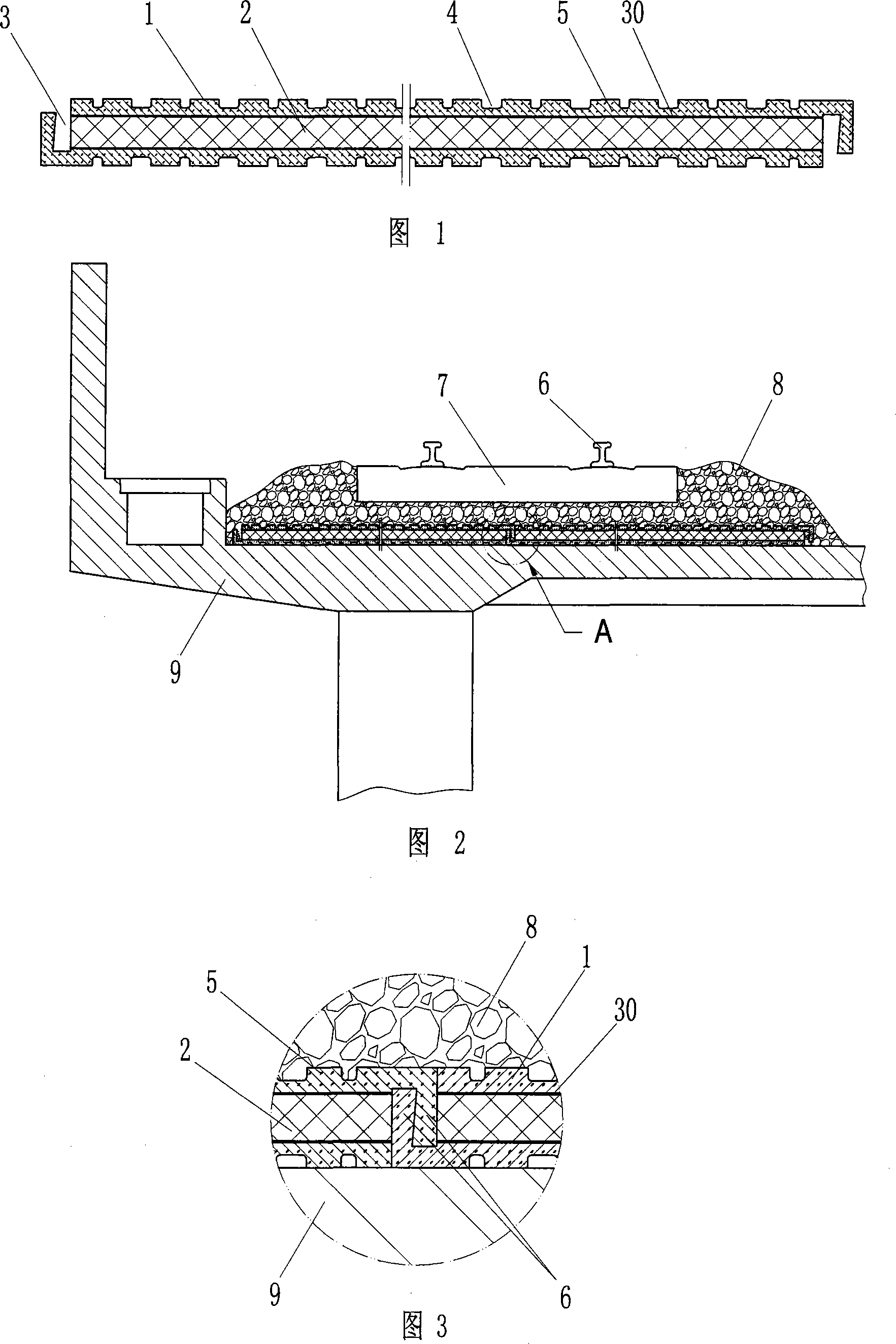
[0033] As shown in Figure 1, the elastic backing plate of the present invention comprises a plate body composed of a wear-resistant elastic layer 1 and a buffer elastic body 2, the buffer elastic body 2 is located between two wear-resistant elastic layers 1, and the wear-resistant elastic layer 1 and the buffer elastic The body 2 is made of rubber, but the elastic modulus of the rubber material used in the buffer elastic body 2 is lower than the elastic modulus of the rubber material used in the wear-resistant elastic layer 1 .
[0034] In order to make the ballast gravel not easy to slide on the backing plate, grooves 4 are arranged on the wear-resistant elastic layer, and the grooves 4 are arranged at intervals of different groove widths. Forming the free side, the plate body can achieve a greater amount of deformation, thereby enhancing the elasticity of the elastic backing plate. In addition, in order to improve the wear resistance and puncture resistance of the elastic ba...
Embodiment 2
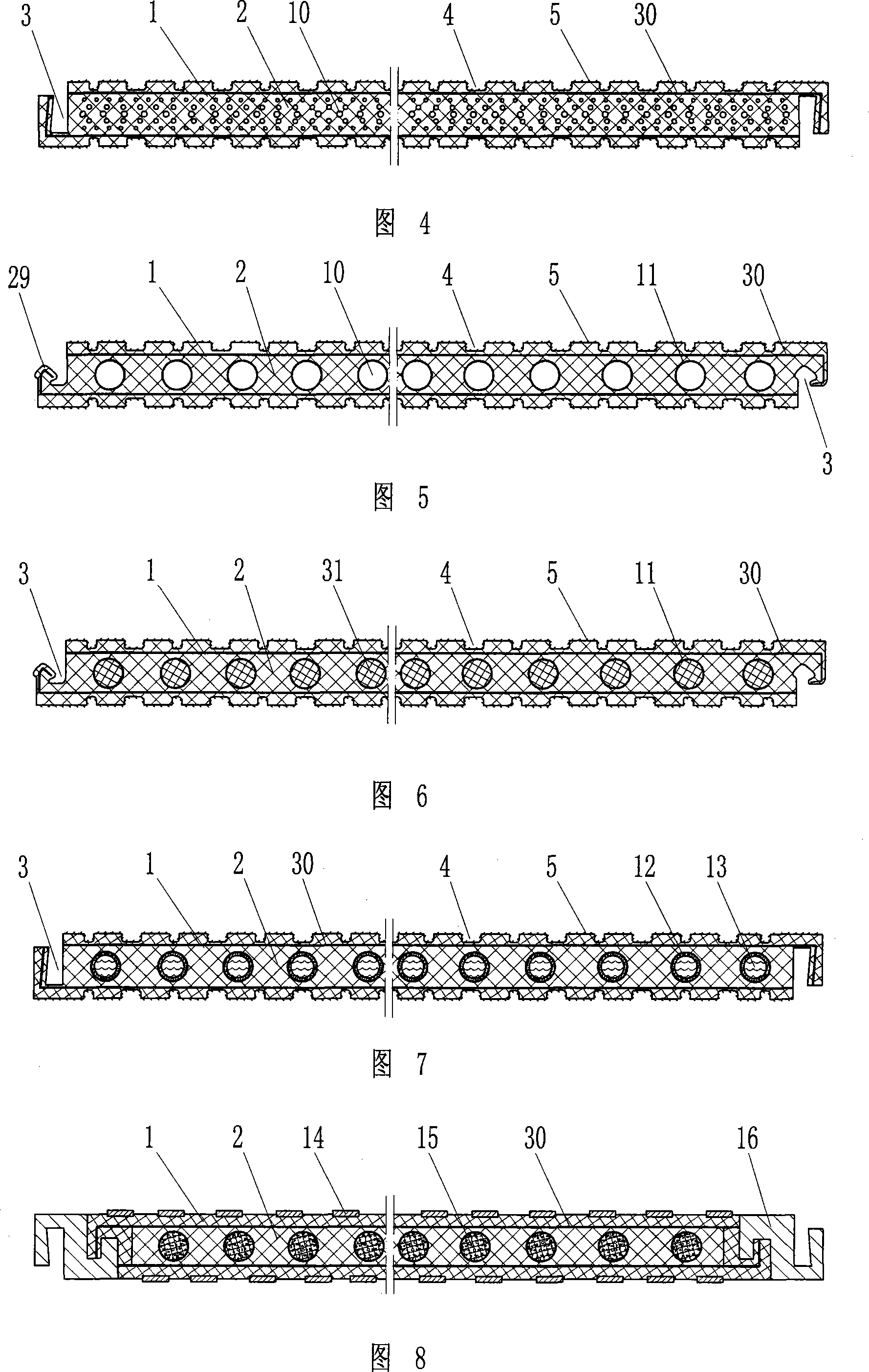
[0038] As shown in Figure 4, the difference between the elastic backing plate of the present invention and Embodiment 1 is that the plate body is made of the same rubber material. In order to increase the elasticity of the backing plate, a multi-layer small cavity 10 is set in the middle of the plate body. The cavity 10 The size is set in the shape of a bone-like section structure that gradually increases from outside to inside. This bionic structure makes the elasticity of the middle part of the plate body significantly higher than that of the upper and lower solid parts, the surface stiffness is lower, and gradually transitions, and the force is more reasonable. This area constitutes the cushioning elastic body 2 of the elastic backing plate of the present invention. In the upper and lower parts of the board body where there is no cavity, the wear-resistant elastic layer 1 is bonded with the wear-resistant reinforcing fiber 5 to form the wear-resistant elastic layer 1 . At t...
Embodiment 3
[0041] As shown in Figure 5, the difference between the elastic backing plate of the present invention and the second embodiment is that a single-layer cavity 10 is set in the middle of the plate body, which increases the elasticity of the middle part of the plate body, and this region constitutes the cushioning elastic body of the elastic backing plate of the present invention. 2. The upper and lower solid regions of the plate constitute the wear-resistant elastic layer 1 . In order to enhance the ability of the cavity 10 to withstand external forces, a tensile and compressive reinforcing material 11 is provided on the cavity wall of the cavity 10, such as a fiber pipe network vulcanized on the cavity inner wall. In order to enhance the connection strength between adjacent elastic backing plates, the plate body is provided with a mushroom-shaped (similar to a floor card slot, more reasonable buckle connection) card slot 3 and a joint 29 .
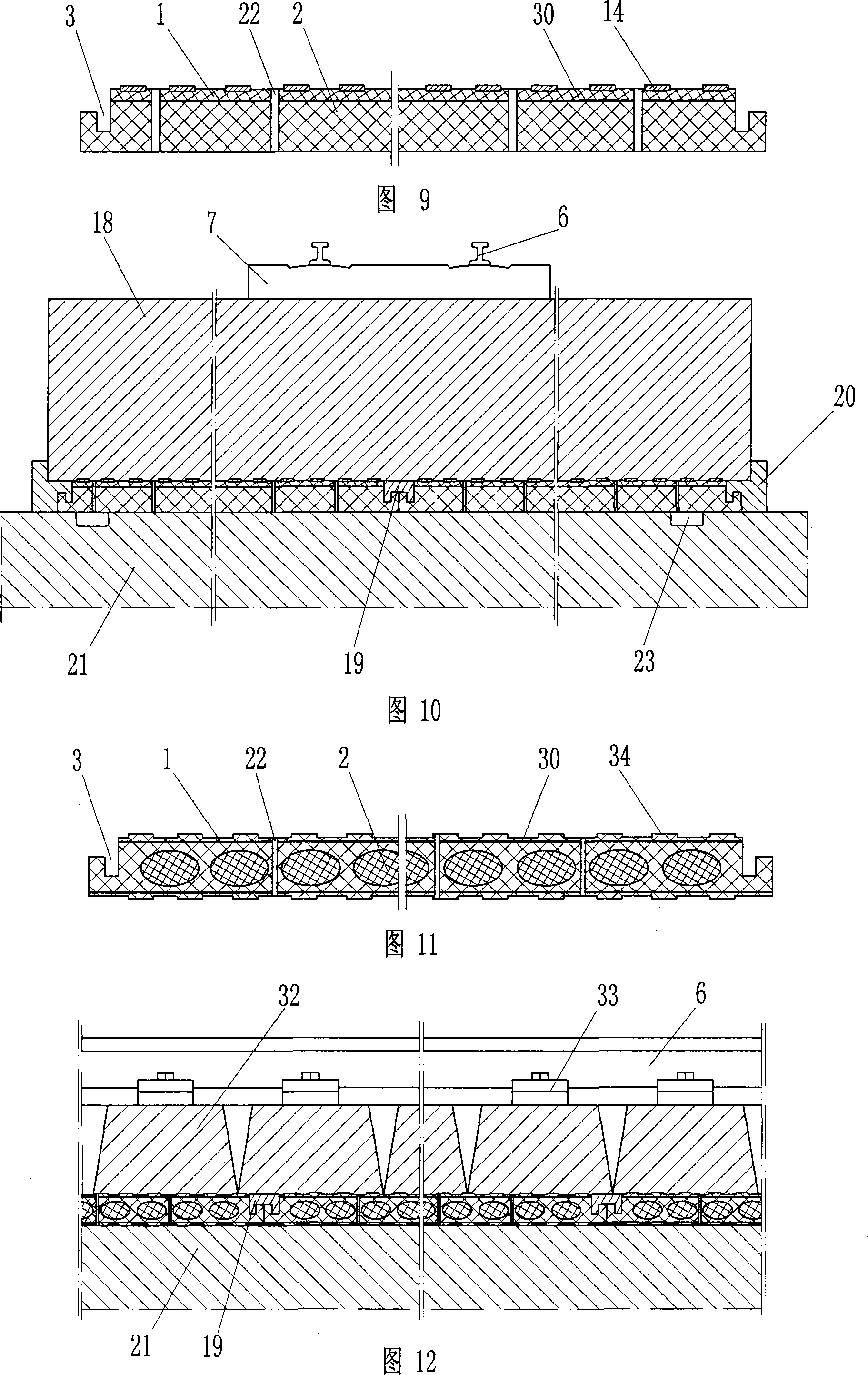
[0042] In addition to the circle me...
PUM
 Abstract
Description
Claims
Application Information