
Built-in rotating machinery operation monitoring protecting equipment and setting method thereof

A technology for rotating machinery and protection devices, applied in the field of rotating machinery operating conditions and intelligent monitoring and protection devices, embedded instruments and settings, can solve the problems of heavy software and hardware development workload, and achieve improved anti-interference performance and reduced prices. Effect

Inactive Publication Date: 2008-03-05
JIANGYIN ZHONGHE POWER METER
View PDF3 Cites 20 Cited by
  • Summary
  • Abstract
  • Description
  • Claims
  • Application Information

AI Technical Summary

Problems solved by technology

But the development of software and hardware is a lot of work
But now there is an urgent need for functions and reliability, and a monitoring and protection system with strong functions

Method used


Image

  • Built-in rotating machinery operation monitoring protecting equipment and setting method thereof
  • Built-in rotating machinery operation monitoring protecting equipment and setting method thereof
  • Built-in rotating machinery operation monitoring protecting equipment and setting method thereof

Examples


Embodiment Construction

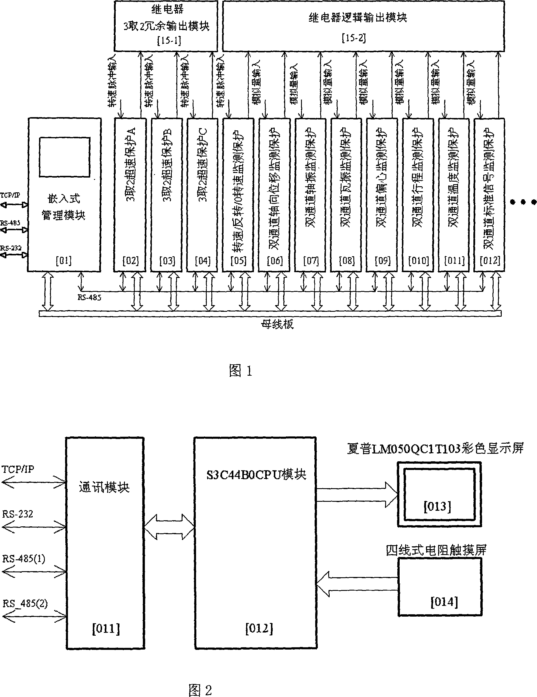
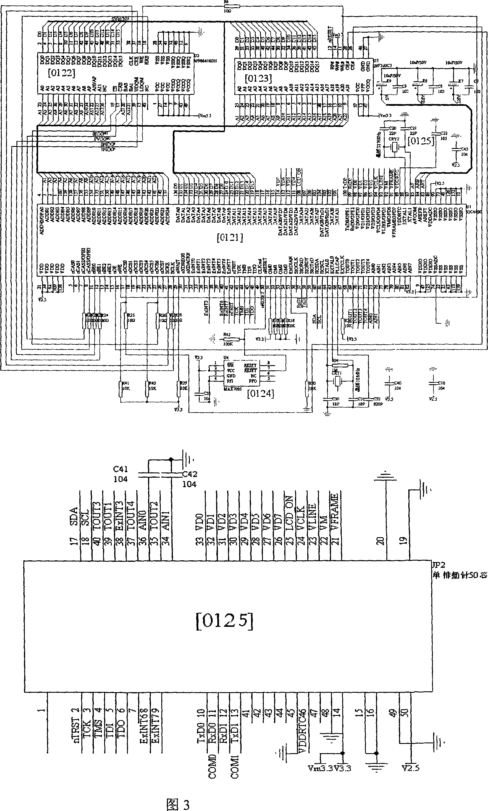
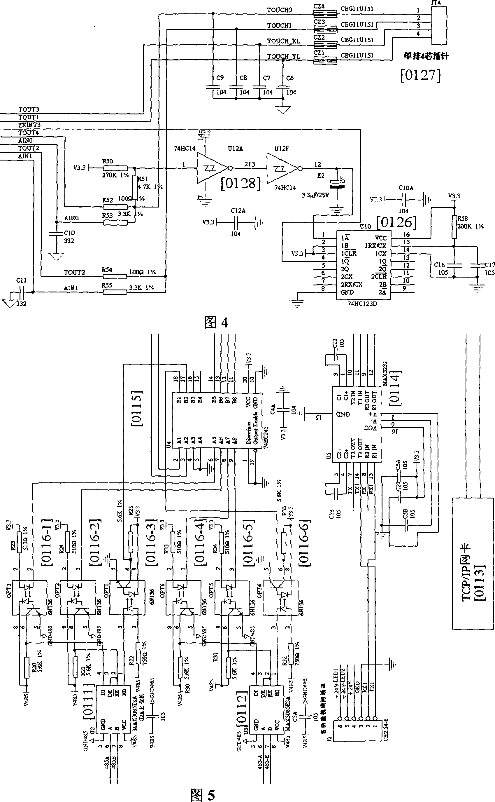
[0047] Embodiment of the setting method of the present invention: mark description in the figure: Fig. 3 has explained management module S3C44B0 embedded CPU module 012; Wherein: processor 0121, dynamic read-write memory SDRAM0122, FLASH solid-state disk 0123, power monitoring 0124, CPU module socket Pin 0125; Figure 4 management module touch screen circuit: monostable trigger 126, touch screen connector 127, Schmitt trigger 128; Figure 5 management module communication interface, communication interface RS-485 0112, RS-232 0114 , network card 0113, buffer 0115; Figure 7 function module LPC2114 embedded CPU circuit, embedded processor 111, A / D converter 112; 113-serial E 2 PROM; [114]-power supply monitoring; in the circuit diagram of the dual-channel 4-20mA current output of the functional module in Fig. 9, optocouplers 161, 162; Schmidt triggers 165, 166; multi-way switch 168; Input, wherein: emitter follower 131, 132; low-pass filter 133, 136; amplification and rectificatio...


PUM


Abstract

The invention uses an embedded computer structure and comprises: an embedded management module, multi functional modules, a display and a touch screen controlling circuit. Each functional module is used for processing the signals from each sensor signal collecting circuit; the embedded management module is used for controlling and transmitting the data through a bus interface circuit connection functional module of high speed universal asynchronous receiver transmitter (UART); said embedded management module has an TCP / IP network interface, a RS232 or RS 485 communication circuit interface; said TCP / IP, RS 232 or RS 485 communication circuit interface are connected to the upper computer to receive the configuration of the upper computer and data collecting command; the output of the embedded management module is connected to the display and touch screen controlling circuit.

Description

technical field [0001] The invention relates to an embedded instrument and a setting method, in particular to a device and a setting method for the operating state of a rotating machine and intelligent monitoring and protection, and belongs to the field of monitoring and protecting the operating state of the machine. Background technique [0002] Many large rotating machinery, mainly including steam turbines, water turbines, generators, motors, compressors, turbines, centrifugal pumps, etc., are key equipment in petrochemical, electric power, metallurgy, coal, nuclear energy and other industries. During mechanical operation, due to factors such as strength, structure, vibration, control reliability, and materials and processes, equipment failures or even damage are often caused, resulting in serious losses. The monitoring and protection of rotating equipment has become a key measure for safe production and economic benefits of enterprises. Therefore, the research on conditi...

Claims


Application Information

Patent Timeline
IPC IPC(8): G05B19/048G05B19/418
CPCY02P90/02
Inventor 方安平刘桂兴徐卫吴冬明
Owner JIANGYIN ZHONGHE POWER METER
Learn More