

Solar full-automatic tracking rotary table
A fully automatic, solar technology, applied in solar thermal power generation, solar thermal devices, non-electric variable control, etc., can solve the problems of high energy consumption, complex mechanical and circuit structures, high cost, etc., and achieve low energy consumption and low market price , The effect of improving the absorption efficiency
- Summary
- Abstract
- Description
- Claims
- Application Information
AI Technical Summary
Problems solved by technology
Method used
Image

Examples
Embodiment Construction
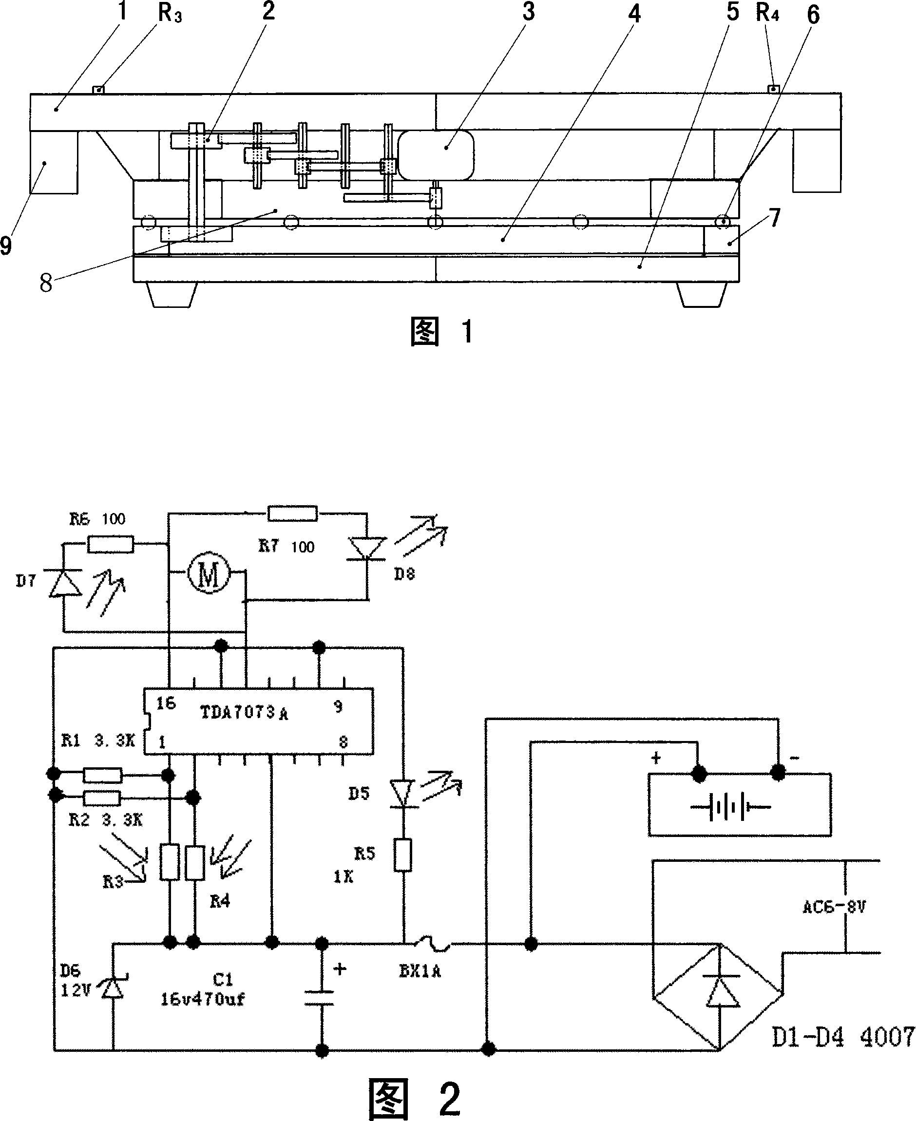
[0016] As shown in Figure 1, the solar energy automatic tracking turntable is composed of upper and lower layers as a whole, and a bottom turntable 4 and a ring gear 7 are fixedly installed on the bottom platform 5 of the tripod of the lower floor. The lower part of the upper working platform 1 is fixed with an upper turntable 8, and its lower surface is processed with ball grooves. The upper surface of the bottom turntable 4 also has a ball groove with the same diameter and coaxiality as the upper turntable 8. Balls 6 are placed in the grooves and supported by the balls 6. The upper turntable 8, the rotation center of the upper turntable 8 is coaxial with the centerline of the ring gear 7, and the relative movement of the upper and lower parts is always kept within the same trajectory of the center of the circle, ensuring a stable relationship between the upper and lower layers , which can not only maximize and effectively reduce the pressure on the upper platform and loads, a...
PUM
 Abstract
Description
Claims
Application Information