Power supply system and switch circuit, switch method of main power source and backup battery

A backup battery and power supply system technology, applied in the direction of power network operating system integration, circuit devices, emergency power supply arrangement, etc., can solve the problem of DC main output power supply efficiency, cannot use MOS field effect transistors, and the second solution limit and other issues to achieve the effect of improving power supply efficiency, reducing energy consumption, and reducing power consumption

Inactive Publication Date: 2008-03-05
SHENZHEN MINDRAY BIO MEDICAL ELECTRONICS CO LTD
View PDF0 Cites 40 Cited by
  • Summary
  • Abstract
  • Description
  • Claims
  • Application Information

AI Technical Summary

Problems solved by technology

[0007] The first scheme is the most widely used scheme, the circuit is simple, but the power supply efficiency is too low
[0008] In the second scheme, when the system needs to use two sets of backup batteries for isolated power supply, it is necessary to ensure the independence of the batteries to prevent the charging and discharging between the batteries due to direct parallel connection between the batteries. Diode isolation is required between the batteries, so that MOS field effect transistors cannot be used to redu

Method used


Image

  • Power supply system and switch circuit, switch method of main power source and backup battery
  • Power supply system and switch circuit, switch method of main power source and backup battery

Examples


Embodiment Construction

[0027] The present invention will be described in further detail below through specific embodiments and in conjunction with the accompanying drawings.

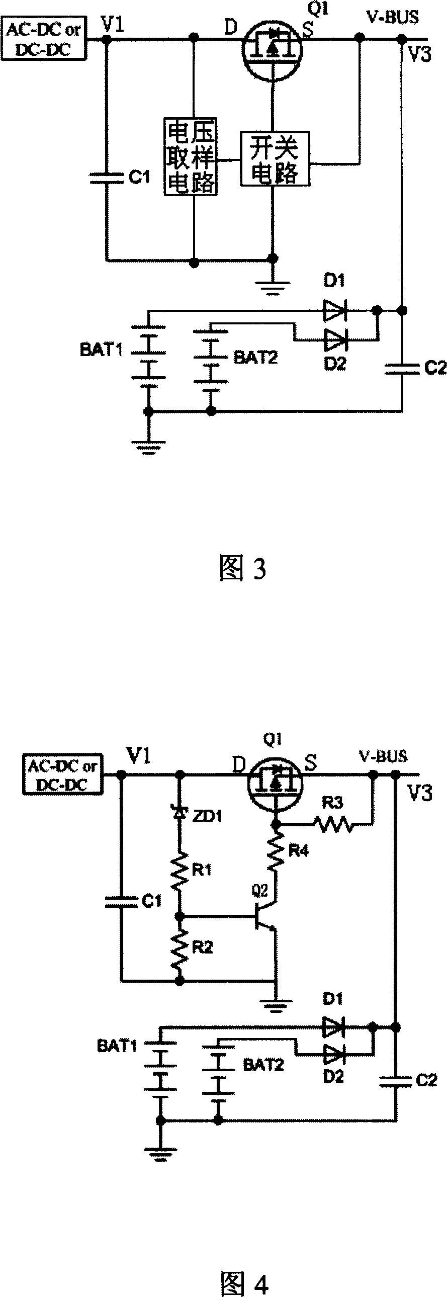
[0028] As shown in FIG. 3 , the power supply system of the present invention includes a main power supply which may be an AC-DC power supply or a DC-DC power supply, a backup battery, and a switching circuit. The switching circuit uses a P-channel MOS field effect tube to connect the DC main output terminal DC of the main power supply and the bus terminal V-BUS, wherein the drain of the P-MOS field effect tube is connected to the DC main output terminal, and the source is connected to the DC main output terminal. At the bus bar end, at this time, the body diode of the P-MOS field effect transistor can be conducted in one direction from the DC end to the bus bar end.

[0029]When the DC main output V1 supplies power, when the DC main output voltage rises higher than the existing voltage V3 on the bus, V1 supplies power to the p...


PUM


Abstract

This invention discloses a power supply system, a switch circuit and a method for its master supply and a standby battery, in which, the switch circuit includes a P-MOS field effect transistor, a voltage sample circuit and a switch circuit, when the sample voltage of the sample end reaches to a preset value or over it, the switch circuit is turned on, its voltage output end outputs control signals to conduct the P-MOS field effect transistor and the DC master output end of the master supply conducts the bus end, when the voltage of the sample end is lower than a preset value, the switch circuit is turned off to stop the field effect transistor and the standby cell supplies to the bus, since the conduction resistance of the P-MOS field effect transistor is low, its voltage drop can be very small and the power loss of the switch circuit is reduced greatly.

Description

【Technical field】 [0001] The invention relates to a power circuit. 【Background technique】 [0002] In the power supply or power supply system with battery backup, when there is a power adapter or other DC power supply, the DC main output of the main power supply (including AC to DC conversion or DC to DC conversion output) is required to supply power to the system, and the DC The main output charges the battery. When the DC main output power supply is interrupted, the battery backup output needs to continue to supply power to the system without interruption. For the system, it is often necessary to realize the uninterrupted switching between the DC main input and the battery input, as well as the isolation of the DC main input and the battery backup input, so as to prevent the backfeeding of the battery voltage to the DC main output. [0003] At present, the main power supply and backup battery switching technologies mainly include: [0004] 1) Diode isolation method: In o...

Claims


Application Information

Patent Timeline
IPC IPC(8): H02J9/06
CPCY02B70/30Y04S20/20
Inventor 唐志杰贾智娱张皖
Owner SHENZHEN MINDRAY BIO MEDICAL ELECTRONICS CO LTD
Why Eureka
Try Eureka