Target surface focal spot monitoring device

A monitoring device and a target surface technology, applied in the field of targeting systems, can solve the problems of small magnification of long focal length microscopes, inability to truly reflect the focal spot condition, low measurement accuracy of the focal spot on the target surface, etc., and achieve convenient optical axis docking and structure Compact, high-precision adjustment effect

Inactive Publication Date: 2008-03-19
SHANGHAI INST OF OPTICS & FINE MECHANICS CHINESE ACAD OF SCI
View PDF0 Cites 7 Cited by
  • Summary
  • Abstract
  • Description
  • Claims
  • Application Information

AI Technical Summary

Problems solved by technology

[0005] 1. The simulated beam aperture provided is much smaller than the actual target beam, which cannot truly reflect the focal spot of the actual target beam after it is focused by the target mirror. Therefore, the simulated beam cannot be used to precisely adjust the position of the target mirror

Method used


Image

  • Target surface focal spot monitoring device

Examples


Embodiment Construction

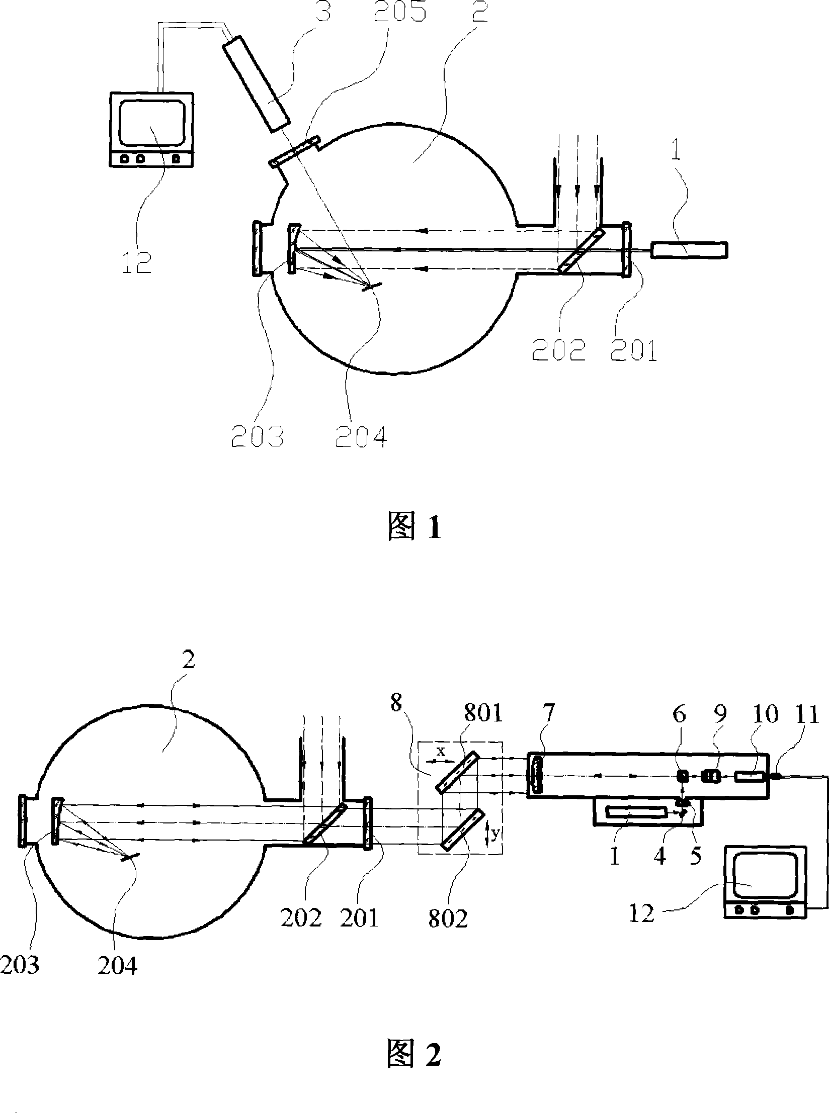
[0024] Please refer to FIG. 2 . FIG. 2 is a schematic structural diagram of the target surface focal spot monitoring device of the present invention. It can be seen from the figure that the target focal spot monitoring device of the present invention includes a parallel laser beam emitting optical path, a target imaging optical path, an optical axis docking system and an image receiving system. The parallel laser beam emitting optical path is used to emit an analog beam, and the target surface imaging optical path receives the scattered light emitted by the focal spot of the target surface to image the target surface, and the optical axis docking system realizes the optical axis and the focal spot monitoring device of the present invention. The docking of the optical axis of the target beam, the image receiving system is used to receive the target surface image formed by the target surface imaging optical path and display it on the monitor. By calculating the size of the focal ...


PUM


Abstract

The present invention provides a target face focal spot monitoring device for laser target practice, and includes a parallel laser beam emitting light path, a target face imaging light path, a ray axis meeting system, and an image receiving system. The parallel laser beam emitting light path is used to emit a simulated laser beam. The target face imaging light path receives the scattered light emitted by the target face focal spot, and forms an image for the target face. The ray axis meeting system realizes the meet of the ray axis of the target face focal spot monitoring device and the ray axis of the target practice beam. The image receiving system is used to receive the image of the target face formed by the target face imaging light path and to display the image on a monitor. By calculating the size of the image of the target face received by a CCD vidicon, the actual size of the target face focal spot can be determined accurately. The device of the present invention can provide a parallel laser beam of which caliber is identical with that of the actual target practice laser beam, simultaneously can also monitor the target spot with a higher magnification to improve the adjustment precision of the target mirror, and then the efficiency of the laser target practice can be improved.

Description

technical field [0001] The invention relates to an aiming system, in particular to a device that provides simulated light beams for an ultrashort and ultrafast laser device and simultaneously monitors a focal spot on a target surface. Background technique [0002] In an ultrashort and ultrafast laser device, the laser beam is focused by the target mirror to form a focal spot on the target surface. The shape, size and position accuracy of the focal spot on the target surface play a key role in the efficiency of laser targeting. , so the adjustment of the target mirror is very important. However, due to the short emission time and high power of the actual target laser beam, it cannot be used as a reference beam for adjusting optical components. Therefore, before shooting a target, the continuously emitted simulated beam is generally used instead of the actual shooting beam as a reference beam to adjust the optical components. [0003] In the prior art, the device with the st...

Claims


Application Information

Patent Timeline
IPC IPC(8): G02B27/00G01M11/00
Inventor 任冰强黄惠杰
Owner SHANGHAI INST OF OPTICS & FINE MECHANICS CHINESE ACAD OF SCI
Why Eureka
Try Eureka