Density disc drive device of automatic light modulation system

A disk drive device and automatic dimming technology, which is applied in control/regulation systems, light control, non-electric variable control, etc., can solve problems such as low adjustment accuracy, inability to control motor speed, and poor anti-disturbance ability

Inactive Publication Date: 2008-03-19
CHANGCHUN INST OF OPTICS FINE MECHANICS & PHYSICS CHINESE ACAD OF SCI
View PDF0 Cites 4 Cited by
  • Summary
  • Abstract
  • Description
  • Claims
  • Application Information

AI Technical Summary

Problems solved by technology

However, this kind of density disk drive device cannot control the motor speed according to the difference in illumination, so the response speed is slow and the adjustment accuracy is low; the reliability of the system is poor under the condition of external environment changes, and the anti-disturbance ability is poor

Method used


Image

  • Density disc drive device of automatic light modulation system
  • Density disc drive device of automatic light modulation system
  • Density disc drive device of automatic light modulation system

Examples


Embodiment 1

[0016] Embodiment 1 (as shown in Figure 5)

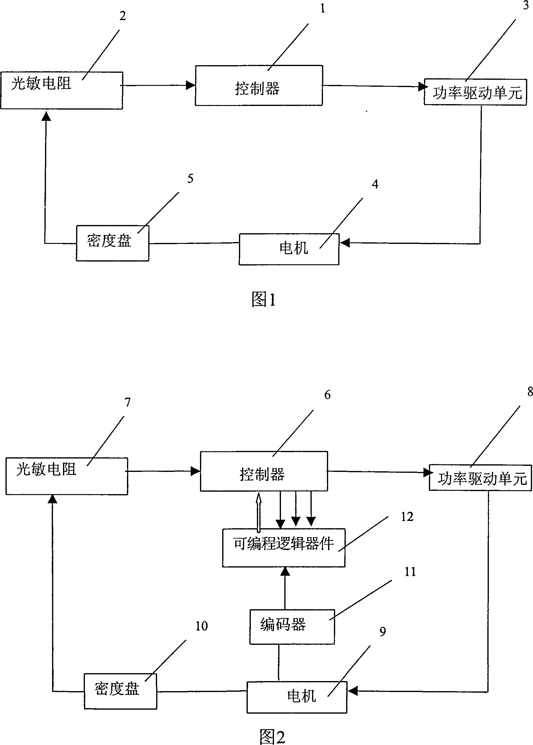
[0017] The present invention comprises a controller 6, a photoresistor 7, a power drive unit 8, a motor 9, an encoder 11, and a programmable logic device 12; Connect the voltage divider circuit, and the other end connects the A / D input of the single-chip microcomputer 18; Input terminal; two output terminals of the power drive unit 8 are respectively connected with the positive and negative ends of the motor 9 power supply; When the value is equal to the standard value, the single-chip microcomputer 18 enables the output to be 0, and the power drive unit 8 has no drive signal output; The power drive unit 8 outputs a drive signal according to the width adjustment wave and direction signal output by the single-chip microcomputer 18, so that the motor 9 rotates forward or reversely, drives the density disc 10 to rotate to adjust the luminous flux, and changes the illuminance value received by the photoresistor 7, thereby reducing the ...

Embodiment 2

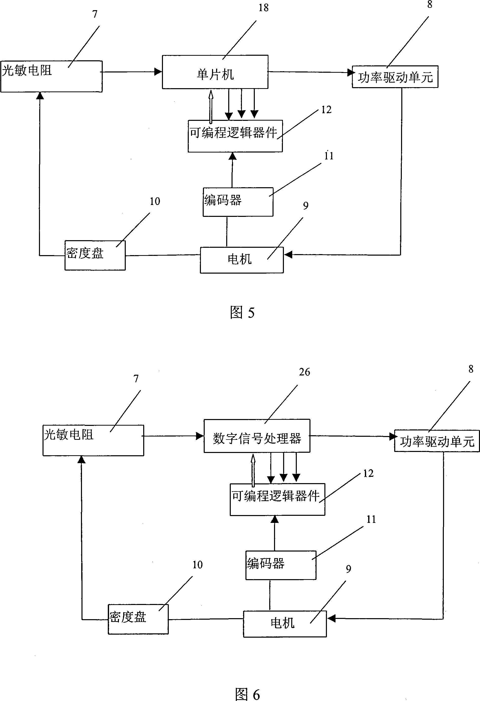
[0020] Embodiment 2 (as shown in Figure 5)

[0021] The present invention includes a controller 6, a photoresistor 7, a power drive unit 8, a motor 9, an encoder 11, and a programmable logic device 12; , one end of which is connected to the voltage divider circuit, and the other end is connected to the A / D input of the digital signal processor 26; the I / O port of the enabling of the digital signal processor 26, the width modulation wave output PWM and the output direction signal are connected to the power drive unit 8 The enabling and input terminals of the power drive unit 8 are respectively connected to the positive and negative terminals of the motor 9 power supply; the digital signal processor 26 reads the divided voltage value on the photoresistor 7 and compares it with the standard value. When the divided voltage value on the photoresistor 7 is equal to the standard value, the digital signal processor 26 enables the output to be 0, and the power drive unit 8 has no drive...

Embodiment 3

[0024] Embodiment 3 (as shown in Figure 6)

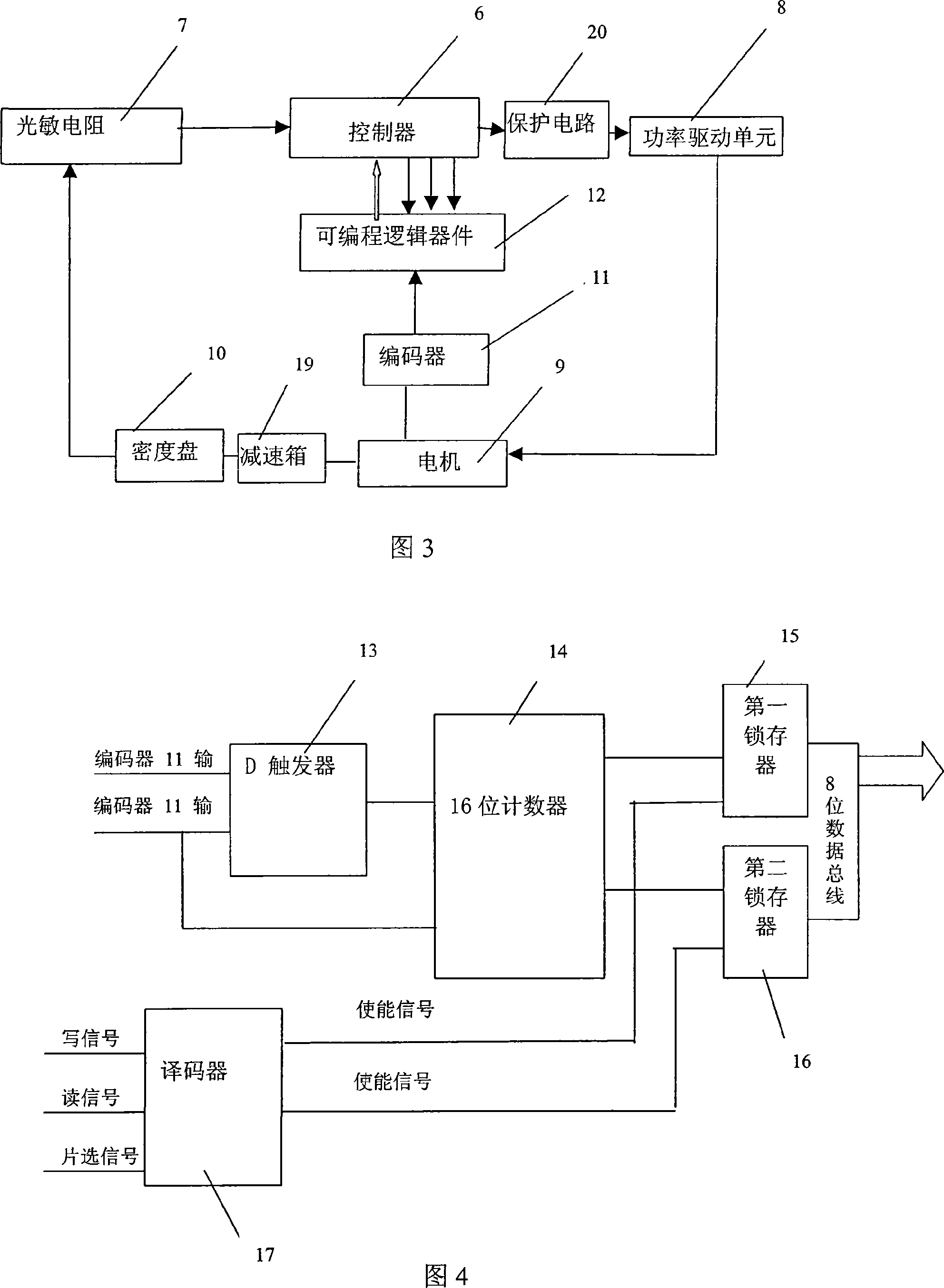
[0025] The present invention includes a controller 6 , a photoresistor 7 , a power drive unit 8 , a motor 9 , a reduction box 19 , an encoder 11 , a programmable logic device 12 and a protection circuit 20 .

[0026] The controller 6 adopts a single-chip microcomputer 18 , and the photoresistor 7 is placed on one side of the density disk 10 , one end of which is connected with a voltage divider circuit, and the other end is connected with the A / D input of the single-chip microcomputer 18 .

[0027] The protection circuit 20 includes a first NOT gate 21, a second NOT gate 22, a third NOT gate 23, a first three-terminal input AND gate 24, and a second three-terminal input AND gate 25; the enabling EN of the microcontroller 18 is directly connected to the power drive An enable input of the unit 8; the width-adjustable wave output HSO.0 of the single-chip microcomputer 18 is simultaneously connected to an input end of the first three-te...


PUM


Abstract

The present invention relates to a density-disk driving device used in a double-loop-controlled automatic lighting system, the device takes a encoder and a counter as speed feedback elements, takes a photosensitive resistor as a position feedback element, and forms a speed-position double-loop system; when the illumination value received by the photosensitive resistor is quite different from the standard value, the dutyfactor of the width wave output by a controller is bigger, the rotating speed of a motor is increased, which rotates the density disk fast; while the illumination value received by the photosensitive resistor is mostly equal to the standard value, the dutyfactor of the width wave output by the controller is smaller, the rotating speed of the motor is reduced, which reduces the speed of the density disk; in this way, on one hand, the illumination flux can reach the standard value in short time; on the other hand, the density disk can be stopped at the correct position to gain the required standard illumination flux, so that the film can get the best contrast. The present invention has fast response and high precision of adjustment.

Description

technical field [0001] The invention relates to an automatic dimming system, in particular to a device for driving a medium-density disk in the automatic dimming system to quickly and constantly adjust the luminous flux in the optical path. Background technique [0002] When the camera is shooting a flying target in the sky, the background illumination of the film frame will also change due to the change of the background brightness of the sky. The purpose of automatic dimming is to automatically adjust the luminous flux to ensure that the illuminance value received on the film is not affected by changes in external light, so that the film can obtain the best contrast. At present, in the automatic dimming system, the motor 4 is generally used as the driving element, and the photoresistor 2 is used as the position feedback element (as shown in Figure 1). When the controller 1 receives the feedback signal from the photoresistor 2, it will Output the width adjustment wave and ...

Claims


Application Information

Patent Timeline
Patent Type & Authority Applications(China)
IPC IPC(8): G05D25/02
Inventor 姜润强王伟国于洪君
Owner CHANGCHUN INST OF OPTICS FINE MECHANICS & PHYSICS CHINESE ACAD OF SCI
Why Eureka
Try Eureka