Backlight module manufacture method

A technology of backlight module and manufacturing method, applied in chemical instruments and methods, optics, nonlinear optics, etc., can solve problems such as multiple time and cost

Inactive Publication Date: 2008-03-26
上海广电光电子有限公司
View PDF0 Cites 18 Cited by
  • Summary
  • Abstract
  • Description
  • Claims
  • Application Information

AI Technical Summary

Problems solved by technology

Such a process req...

Method used


Image

  • Backlight module manufacture method
  • Backlight module manufacture method

Examples


Embodiment Construction

[0022] The present invention will be further described below in conjunction with the drawings and specific embodiments.

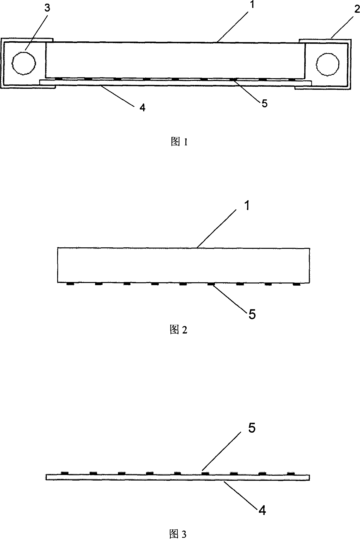
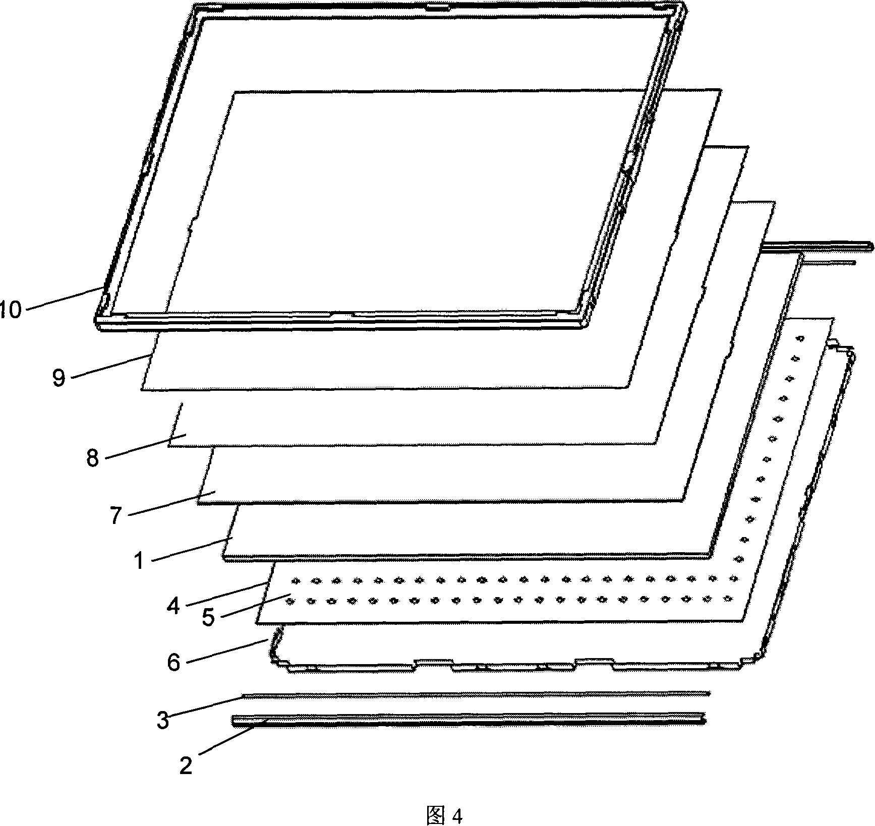
[0023] 3 and 4 show a backlight module containing two cold cathode lamp tubes, and the thickness of the light guide plate 1 is 4 mm. It consists of a light guide plate 1, two lamp tube reflectors 2, two lamp tubes 3, a reflection sheet 4, a back plate 6, a lower diffusion sheet 7, a prism sheet 8, an upper diffusion sheet 9 and a plastic frame 10. Different from the traditional process, when making the light guide plate, the light guide dots are not printed on one side surface of the light guide plate, but the light guide dots 5 are printed on one side surface of the reflective sheet 4 with ink added with adhesive. (The cross-section is shown in Figure 3), and then cover it with release paper, and store or transport it for module assembly. When the backlight module is assembled, the release paper is torn off and the side of the reflective sheet 4 with the light...


PUM


Abstract

This invention discloses a sort of manufacturing method of the back-light module, and this module consists of the light board and the reflector plate. This method makes the light halftone dot to be fixed in the surface of the firing plate, and it makes the face of the reflector plate which has the light halftone dot to be glued in the light board close in the assembly of the back-light module. The manufacturing working procedure which adopts this invention is convenient, it saves the space of the manufacture, it is propitious to advance the manufacturing efficiency, it advances the crop, and its cost is low correspondingly.

Description

Technical field [0001] The invention relates to a method for manufacturing a liquid crystal display device assembly, and in particular to a method for manufacturing a liquid crystal display backlight module. Background technique [0002] TFT-LCD (Thin Film Transistor Liquid Crystal Display) is widely used in computers, communication equipment and other various display devices. A general liquid crystal display is mainly composed of a liquid crystal panel and a backlight module. The backlight module can be divided into two types: side-light type and direct-light type according to different light source distribution positions. [0003] Most liquid crystal displays adopt edge-lit backlight module structure. The light source is arranged on the side of the light-incident surface of the light guide plate. The light source directly or indirectly enters the light guide plate and spreads. After the total reflection phenomenon is destroyed by the optical dots and the reflective sheet under ...

Claims


Application Information

Patent Timeline
IPC IPC(8): G02F1/13357G02F1/1333B32B37/12G02F1/1335
Inventor 胡秋霞王丹
Owner 上海广电光电子有限公司
Why Eureka
Try Eureka