Field generating unit of a combined MR/PET system

A generating unit, combined technology, used in magnetic resonance measurement, computed tomography, diagnosis, etc., can solve the problems of infeasible matching of patient diameters, difficult antenna device establishment and disassembly, etc., to achieve simple and effective as small as possible. Attenuation, saving computation time, effect of time saving

Inactive Publication Date: 2008-04-02
SIEMENS AG
View PDF1 Cites 18 Cited by
  • Summary
  • Abstract
  • Description
  • Claims
  • Application Information

AI Technical Summary

Problems solved by technology

[0007] In combined MR-PET systems, however, the use of local coils has different disadvantages: On the one hand, local coil placement requires the operator up to five minutes per patient for positioning and later removal of the local coil
Therefore, the installation and remo

Method used


Image

  • Field generating unit of a combined MR/PET system
  • Field generating unit of a combined MR/PET system
  • Field generating unit of a combined MR/PET system

Examples


Embodiment Construction

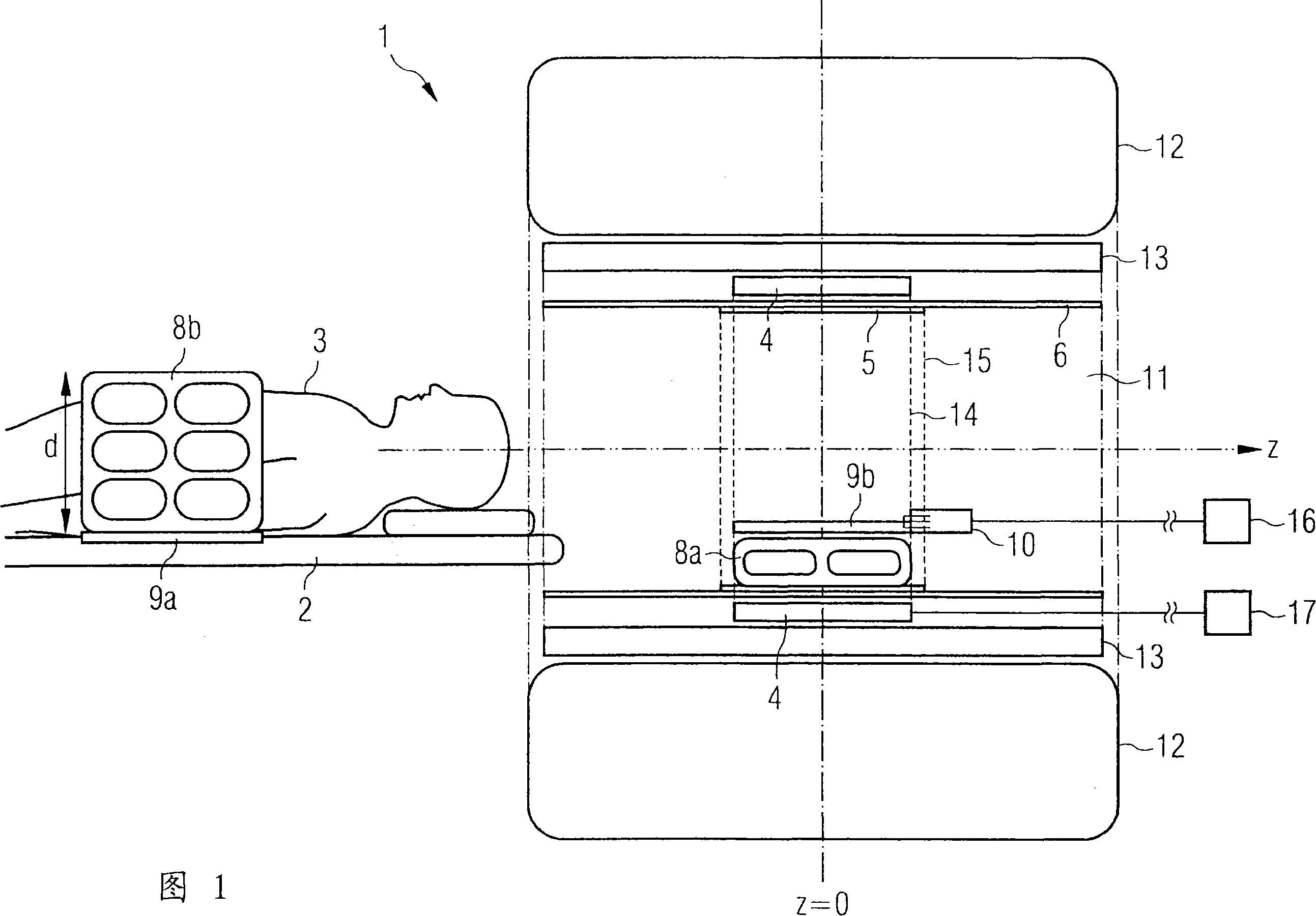
[0033] In FIG. 1 , the magnetic field generating unit 1 is shown in a longitudinal section through the Z axis (indicated by a two-dot chain line). In the center of the examination tunnel 11 at Z=0 there is a substantially uniform magnetic field in the Z direction, so that MR imaging takes place there.

[0034] Gradient fields are generated by gradient coils 13 . Radially further inward is arranged a PET detector ring 4 also centered on Z=0. Further inwards follows a support tube 6 for an external HF antenna arrangement or whole-body antenna 5 . Such a whole-body antenna 5 is preferably used for overview recording and as a transmitting antenna. The image field 14 of the PET detector ring and the image field 15 of the whole-body antenna 5 overlap each other as far as possible.

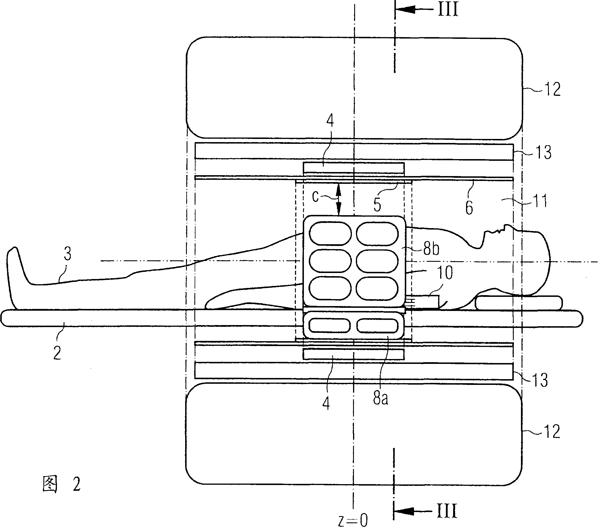
[0035] The magnetic field generating unit 1 also includes a lower part 8 a of the inner HF antenna arrangement 8 . The part 8a is arranged such that it is arranged below the couch when the couch 2 is...


PUM


Abstract

The invention relates to a special HF antenna arrangement for a combined MR-PET device. The HF antenna device has a first part (8a), which is installed fixedly with the equipment in the inspection tunnel (11) so that it is arranged below the couch (2) when the couch (2) is driven in; The HF antenna device also has a second part (8b), which can be placed on the couch (2) and can move into and out of the inspection tunnel (11) along with the couch, wherein the internal HF The second part (8b) of the antenna arrangement is designed rigidly and has a clear cross section (d) adapted to the cross section of the object to be examined (3). As a result, the time outlay for installing the RF antenna is reduced and a correction of the gamma ray attenuation is made possible by the fixed state of the RF antenna. Furthermore, a plurality of second parts (8b) having different diameters may be provided.

Description

technical field [0001] The invention relates to the combination of the medical imaging methods MR or MRT (Magnetic Resonance Tomography) and PET (Positron Emission Tomography) in one device. More specifically, it relates to a magnetic field generating unit of a combined MR-PET apparatus having a main magnet for generating a constant magnetic field within an examination tunnel and a PET detector ring radially surrounding the examination tunnel. The object to be examined can be introduced into the examination tunnel on a movable table. Background technique [0002] Magnetic resonance tomography (MR or MRT) is an imaging method used to represent tissues in the human or animal body. MRT is based on the principle of nuclear spin resonance, according to which atomic nuclei (such as hydrogen nuclei present in large quantities in the body) have a magnetic moment. Due to this magnetic moment, the atomic nuclei can be excited by electromagnetic radiation in the high-frequency range ...

Claims


Application Information

Patent Timeline
IPC IPC(8): A61B5/055A61B6/03G01R33/32
CPCG01R33/481G01R33/3415
Inventor 路德维格·埃伯勒拉兹万·拉扎尔于尔根·尼斯特勒沃尔夫冈·伦兹诺伯特·里奇
Owner SIEMENS AG
Why Eureka
Try Eureka