Technique for reverting ironmaking by comprehensive utilization of fusion of coal gas and small ore

A technology for reducing iron and gas, applied in the direction of reducing gas emissions, furnace types, furnaces, etc., can solve the problems of low gas utilization, low production efficiency, and reduced reaction efficiency of multi-stage fluidized beds, and achieve the goal of preventing carbon precipitation reaction Effect

Active Publication Date: 2008-04-02
XINJIANG BAYI IRON & STEEL
View PDF0 Cites 22 Cited by
  • Summary
  • Abstract
  • Description
  • Claims
  • Application Information

AI Technical Summary

Problems solved by technology

[0005] The smelter-gasification final reduction furnace of the two-step smelting reduction ironmaking process is mature, with high production capacity and efficiency, but currently a single fluidized bed or shaft furnace is used as the pre-reducer to become the limiting link of the smelting reduction process
Using the shaft furnace as the pre-reduction device has high overall energy consumption and low production efficiency, and requires the...

Method used


Image

  • Technique for reverting ironmaking by comprehensive utilization of fusion of coal gas and small ore
  • Technique for reverting ironmaking by comprehensive utilization of fusion of coal gas and small ore
  • Technique for reverting ironmaking by comprehensive utilization of fusion of coal gas and small ore

Examples


Embodiment 1

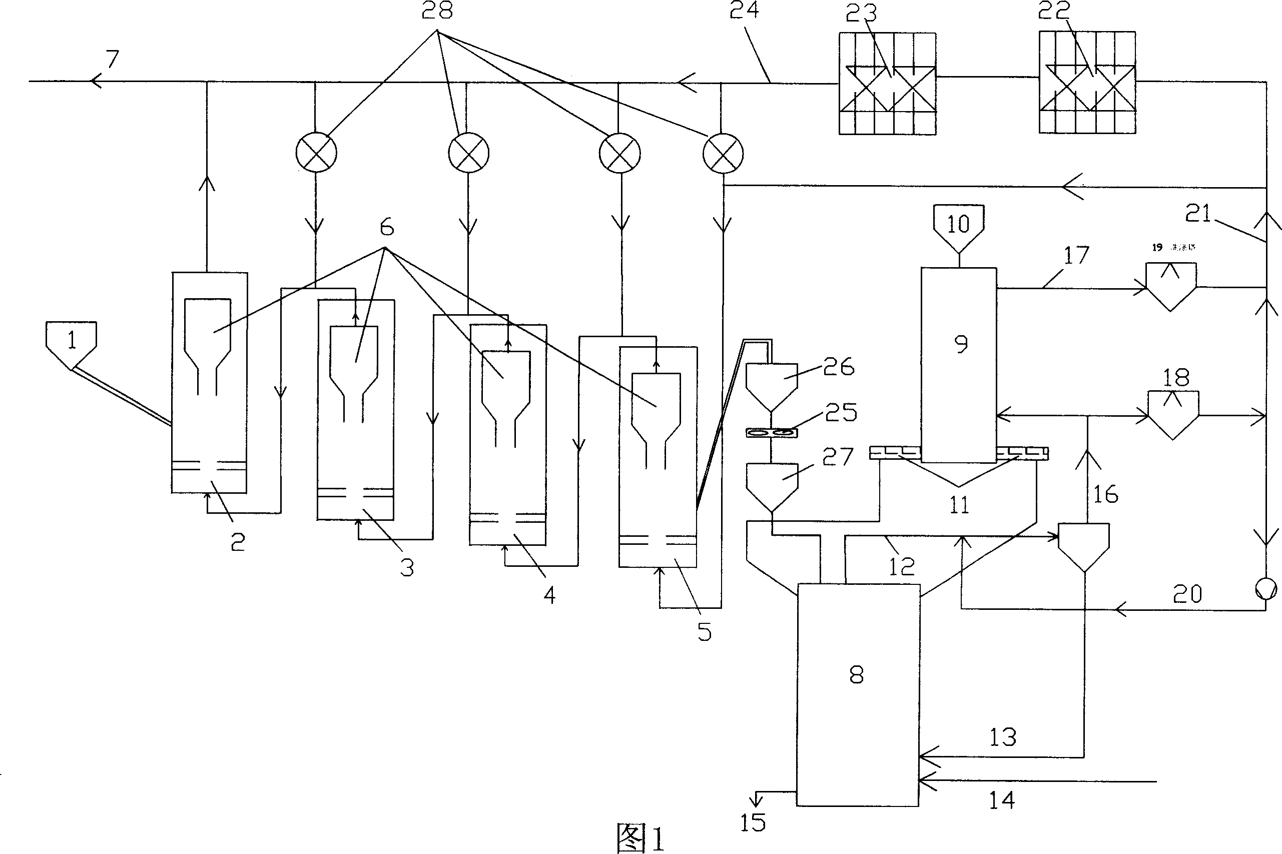
[0028] Referring to Fig. 1, powdered ore (particle size8mm) materials are respectively installed in powder ore silo 1 and lump ore silo 10, and are filled with lump coal and lump ore for melting and gasification Oxygen 14 (purity > 99%) is injected into the furnace 8. Under high temperature conditions, the coal in the melting and gasification furnace 8 forms semi-coke and produces a large amount of reducing export gas 12. The outlet gas 12 passes through the cyclone dust collector 16 to separate the gas The dust 13 in is returned to the melter-gasifier 8 for reaction. Part of the gas that has been dedusted by the cyclone is passed into the shaft furnace 9 to reduce the lump ore added from the lump ore silo 10, and DRI with a reduction degree of 70-95% of the lump ore reduced by the shaft furnace is added through the screw feeder 11 Separation of the final reduced slag and iron 15 in the melting and gasifier to obtain qualified molten iron whose quality is comparable to that of...

Embodiment 2

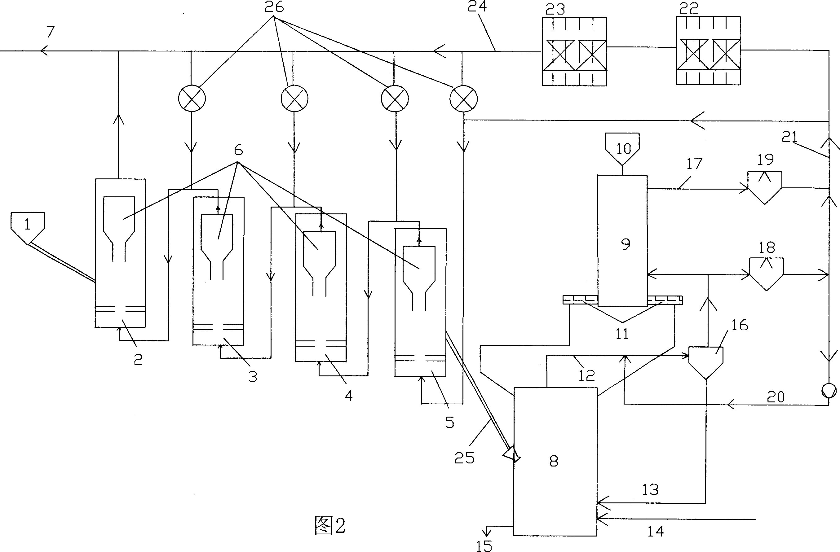
[0032] Referring to Fig. 2, powdered ore (particle size8mm) materials are respectively installed in powder ore silo 1 and lump ore silo 10, and are filled with lump coal and lump ore for melting and gasification Oxygen 14 (purity > 99%) is injected into the furnace 8. Under high temperature conditions, the coal in the melting and gasification furnace 8 forms semi-coke and produces a large amount of reducing export gas 12. The outlet gas 12 passes through the cyclone dust collector 16 to separate the gas The dust 13 in is returned to the melter-gasifier 8 for reaction. Part of the gas that has been dedusted by the cyclone is passed into the shaft furnace 9 to reduce the lump ore added from the lump ore silo 10, and DRI with a reduction degree of 70-95% of the lump ore reduced by the shaft furnace is added through the screw feeder 11 Separation of the final reduced slag and iron 15 in the melting and gasifier to obtain qualified molten iron whose quality is comparable to that of...

Embodiment 3

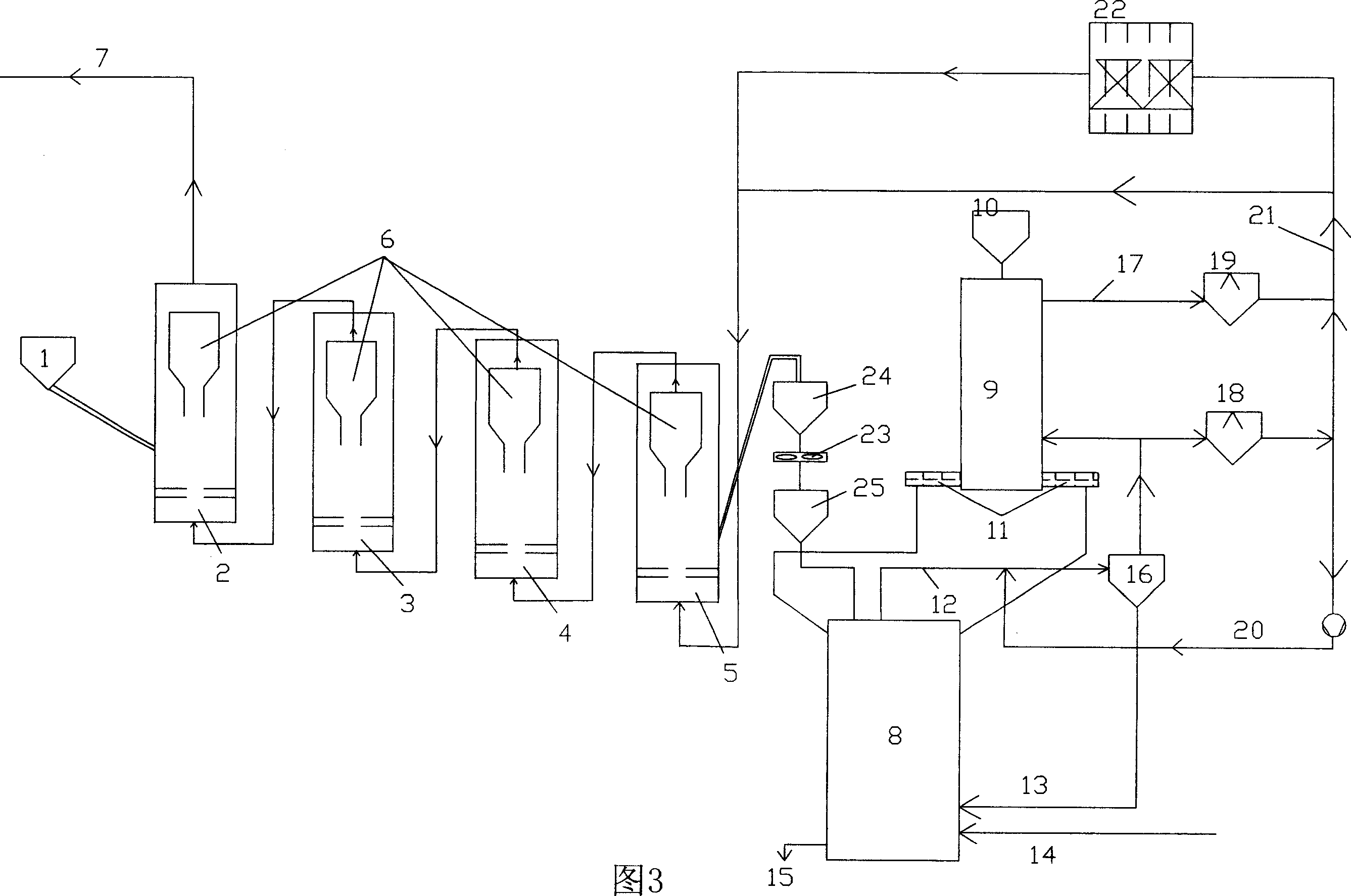
[0037] Referring to Fig. 3, powdered ore (particle size8mm) materials are respectively installed in powder ore silo 1 and lump ore silo 10, and are filled with lump coal and lump ore for melting and gasification Oxygen 14 (purity > 99%) is injected into the furnace 8. Under high temperature conditions, the coal in the melting and gasification furnace 8 forms semi-coke and produces a large amount of reducing export gas 12. The outlet gas 12 passes through the cyclone dust collector 16 to separate the gas The dust 13 in is returned to the melter-gasifier 8 for reaction. Part of the gas that has been dedusted by the cyclone is passed into the shaft furnace 9 to reduce the lump ore added from the lump ore silo 10, and DRI with a reduction degree of 70-95% of the lump ore reduced by the shaft furnace is added through the screw feeder 11 Separation of the final reduced slag and iron 15 in the melting and gasifier to obtain qualified molten iron whose quality is comparable to that of...


PUM


Abstract

A melting reduction iron making technology with comprehensive utilization of gas and fine ore, and the technological procedures are as follows: firstly the oxygen delivered into the melting gasification final reduction furnace undergoes the gasification reaction with the gas filled into the melting gasification furnace, to generate the reductive gas, secondly the gas yielded by the melting gasification final reduction furnace is delivered into a shaft furnace to reduce the block ore, thirdly the residue gas yielded by the melting gasification final reduction furnace is mixed with the gas output by the shaft furnace, then CO2 is eliminated through water/gas conversion and pressure-variation absorption to obtain the mixed gas containing hydrogen for treatment of the raw material of fine core by a multi-stage fluidized bed reactor and, fourthly the directly reduced power iron produced in the form of thermal pressed block after being processed by the multi-stage fluidized bed reactor, and the directly reduce iron sprayed into the melting gasification furnace or produced by the shaft furnace are reduced finally into the melted iron in the melting gasification final reduction furnace. The present invention combines the advantages of both the shaft furnace and the fluidized bed reactor, uses the shaft furnace and the fluidized bed reactor as the reduction reactor at the same time, improves the comprehensive capability in the pre-reduction process of the melting reduction techniques, and accomplishes the comprehensive utilization of the resource of fine ore and the block ore.

Description

technical field [0001] The invention relates to a smelting reduction ironmaking process in the ironmaking field, in particular to a method for smelting molten iron by comprehensively utilizing gas, lump ore and fine ore resources generated in the smelting reduction process. Background technique [0002] Smelting reduction smelting molten iron technology is a new technology to replace the current blast furnace smelting molten iron with long process flow, serious pollution and must use metallurgical coke. The smelting reduction process can be generally divided into one-step smelting reduction process and two-step smelting reduction process. [0003] The smelting reduction method in which the entire smelting process is completed in one step in one reactor is called "one-step method". The heat is effectively transferred to the reduction zone, and at the same time, the reduction zone should be prevented from being oxidized; in addition, the high (FeO) slag produced by smelting re...

Claims


Application Information

Patent Timeline
IPC IPC(8): C21B13/02C22B1/14C22B5/10C22B5/12
CPCY02P10/122
Inventor 范建峰周渝生李维国
Owner XINJIANG BAYI IRON & STEEL
Why Eureka
Try Eureka