Integrated electric valve

A technology for electric valves and shells, which is applied to valve details, valve devices, engine components, etc. It can solve the problems of many external connections of electric valves, poor matching of refrigeration equipment, and affecting the life of components, so as to achieve simple internal connections and reduce Effects of interference and radiation, prolonging component life

Inactive Publication Date: 2008-04-09
蒋庆
View PDF2 Cites 3 Cited by
  • Summary
  • Abstract
  • Description
  • Claims
  • Application Information

AI Technical Summary

Problems solved by technology

[0003] The present invention mainly solves the technical problems that the existing electric valve has many external connections, complex control, large interference and radiation, poor matching with refrigeration equipment, and brings a lot of inconvenience to the assembly of refrigeration equipment; it provides a kind of electric valve with few external connections, The integrated electric valve is simple to control, effectively reduces interference and radiation, and is well matched with refrigeration equipment, which is convenient for the assembly of refrigeration equipment.
[0004] The present invention also solves the technical problem that excessive reversal hits the limit mechanism when the stepper motor of the existing electric valve returns to the zero position, causing high noise and affecting the life of the components; it provides a corresponding angle of reversal when the stepper motor returns to the zero position , so as to reduce the impact on the limit mechanism, ensure the integrated electric valve with low noise and prolong the life of the components

Method used


Image

  • Integrated electric valve
  • Integrated electric valve
  • Integrated electric valve

Examples


Embodiment 1

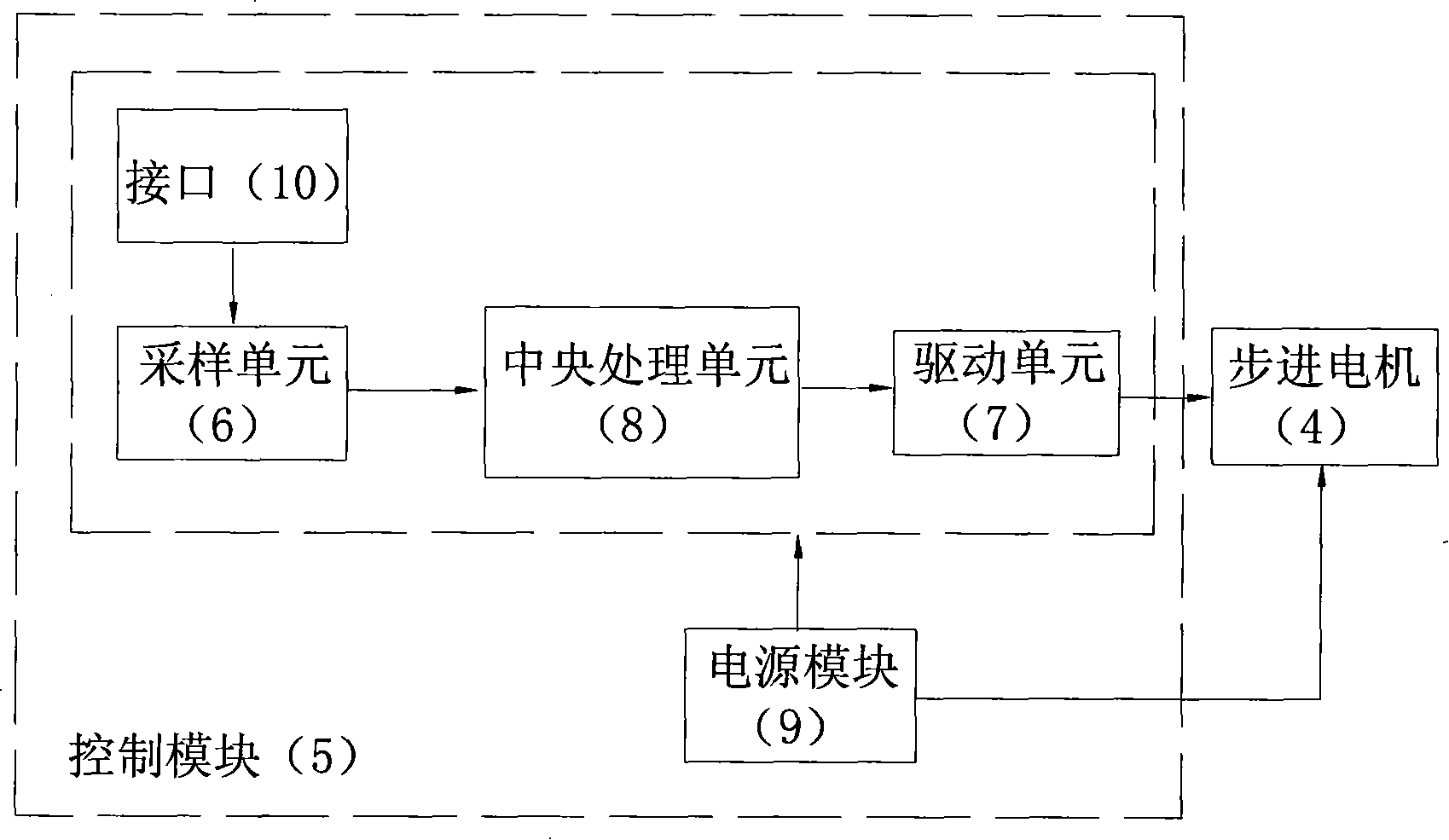
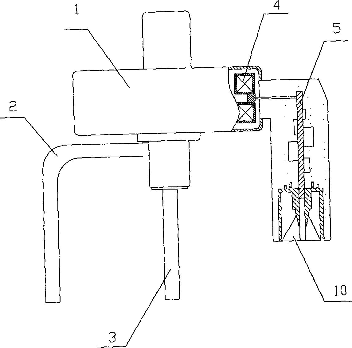
[0021] Embodiment 1: the integrated electric valve of this embodiment, such as image 3 As shown, a stepper motor 4, a control module 5, and a valve cavity connected with an inlet pipe 2 and an outlet pipe 3 are integrally packaged in the housing 1, and the outlet pipe 3 is located at the mouth of the housing 1 and is installed with a stepper motor. Into the valve mechanism connected to motor 4. Such as figure 1 As shown, the control module 5 includes a central processing unit 8 connected with a sampling unit 6, a drive unit 7, and a power supply module 9 that provides operating power for the entire valve. The drive unit 7 is connected to the stepper motor 4 through a stepper motor interface. A three-core interface 10 is installed on the body 1, one core of the three-core interface 10 is connected to the sampling unit 6, and the other two cores are connected to the power module 9, and the central processing unit 8 stores a control program. The matching between the valve and ...

Embodiment 2

[0029] Embodiment 2: the integrated electric valve of this embodiment, such as Figure 5 As shown, a stepper motor 4, a control module 5, and a valve cavity connected with an inlet pipe 2 and two outlet pipes 3 are integrally packaged in the housing 1, and the outlet pipe 3 is located at the mouth of the housing 1 and installed with a The stepping motor 4 is connected to the valve mechanism. A four-core interface 10 is installed on the housing 1 , two cores of the four-core interface 10 are connected to the sampling unit 6 , and the other two cores are connected to the power module 9 . All components on the control module 5 in the present embodiment are welded on a circuit board, as Figure 6 As shown, the sampling unit 6 is composed of resistors R1, R2, and capacitors C5 and C6. The two control signals input by the refrigeration equipment control part are input through the interface JP2 and the two resistance values ​​of R1 and R2 are pulled up respectively. The two input si...


PUM


Abstract

The invention relates to an integrated electric valve. A stepping motor, a control module and a valve cavity which is connected with an induction tube and a plurality of eduction tubes are encapsulated in a housing of the valve. A valve mechanism connected with the stepping motor is arranged at a tube mouth where the eduction tube and the valve cavity are connected. The control module comprises a central processing unit which is connected with a sampling unit and a drive unit and a power module supplying working power to the entire valve. The drive unit is connected with the stepping motor. The sampling unit is provided with one or two signal input lines for a TTL level contact signal or voltage and current signals. The central processing unit is stored with control programs which ensure the smooth and stable returning to zero of a rotor. The rotor winding is provided with drive pulse only when rotating and is zero consumption when still, saving energy effectively. The control strategy of the stepping motor of the invention is implemented by the control module in the valve, thus the matching of the valve with refrigerating equipment is ensured and the assembly of the refrigerating equipment is facilitated, increasing remarkably the production efficiency.

Description

technical field [0001] The invention relates to an electric valve, in particular to an integrated electric valve. Background technique [0002] At present, in the refrigeration industry, there are electronic expansion valves and electric switching valves for regulating the flow and direction of refrigerant, such as an "electronic expansion valve" disclosed in Chinese patent document CN200410093130.0, and a kind of electronic expansion valve disclosed in Chinese patent document CN200510060210.0. "Electric switching valve", these two valves use the principle of stepping motors, use coils to drive the rotor parts to rotate, and then change the flow area of ​​the valve port or change the on-off relationship between the inlet port and multiple outlets through a certain transmission mechanism. In this way, the refrigerant flowing through the valve port is consistent with the predetermined flow-pulse curve or the refrigerant flows to the designated outlet to realize flow and flow d...

Claims


Application Information

Patent Timeline
Patent Type & Authority Applications(China)
IPC IPC(8): F16K31/04F25B41/06
CPCY02B30/72Y02B30/70
Inventor 蒋庆汤建斌蔡晋辉
Owner 蒋庆
Why Eureka
Try Eureka