
Strong anti-block automatic pollution discharge breast wall type backflow device

An automatic sewage and anti-clogging technology, applied in heating devices, geothermal power generation, other non-combustion heat generation, etc., can solve the problems of well wall collapse, abandoned wells, sand removal, etc., to improve service life, stable and reliable operation, Reasonable effect of structural design

Inactive Publication Date: 2008-04-09
靖洪铭 +1
View PDF7 Cites 3 Cited by
  • Summary
  • Abstract
  • Description
  • Claims
  • Application Information

AI Technical Summary

Problems solved by technology

[0003] The purpose of the present invention is to provide a strong anti-clogging automatic sewage discharge wall protection type refilling device, which can fundamentally solve the problems of sand removal at the bottom of the pumping well of a single-tube well or multi-tube well, well wall collapse and waste well, etc. Compared with the blockage automatic sewage refilling device, in addition to retaining its thorough desilting effect and timely refilling characteristics, it also has the advantages of more reasonable structural design, more stable and reliable operation, and further improves the service life of the heat collection well and prevents blockage. Irrigation effect, effectively avoiding single-tube wells or multi-tube wells from becoming waste wells

Method used


Image

  • Strong anti-block automatic pollution discharge breast wall type backflow device
  • Strong anti-block automatic pollution discharge breast wall type backflow device
  • Strong anti-block automatic pollution discharge breast wall type backflow device

Examples


Embodiment Construction

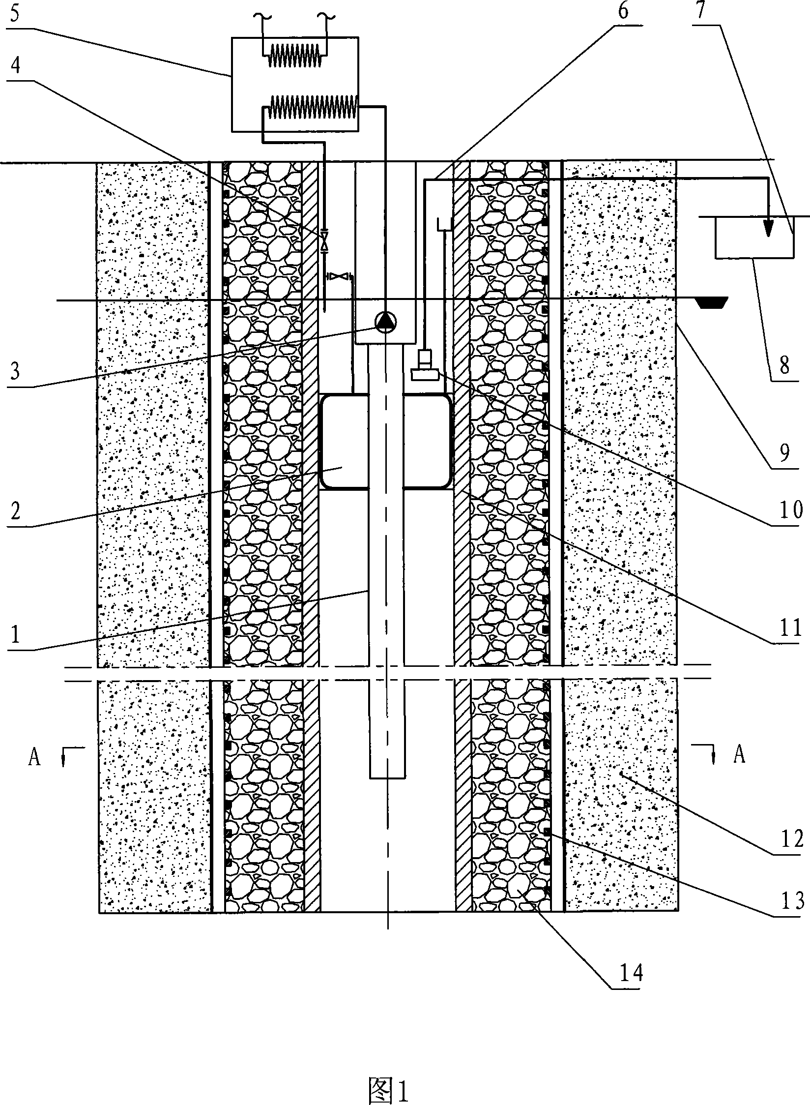
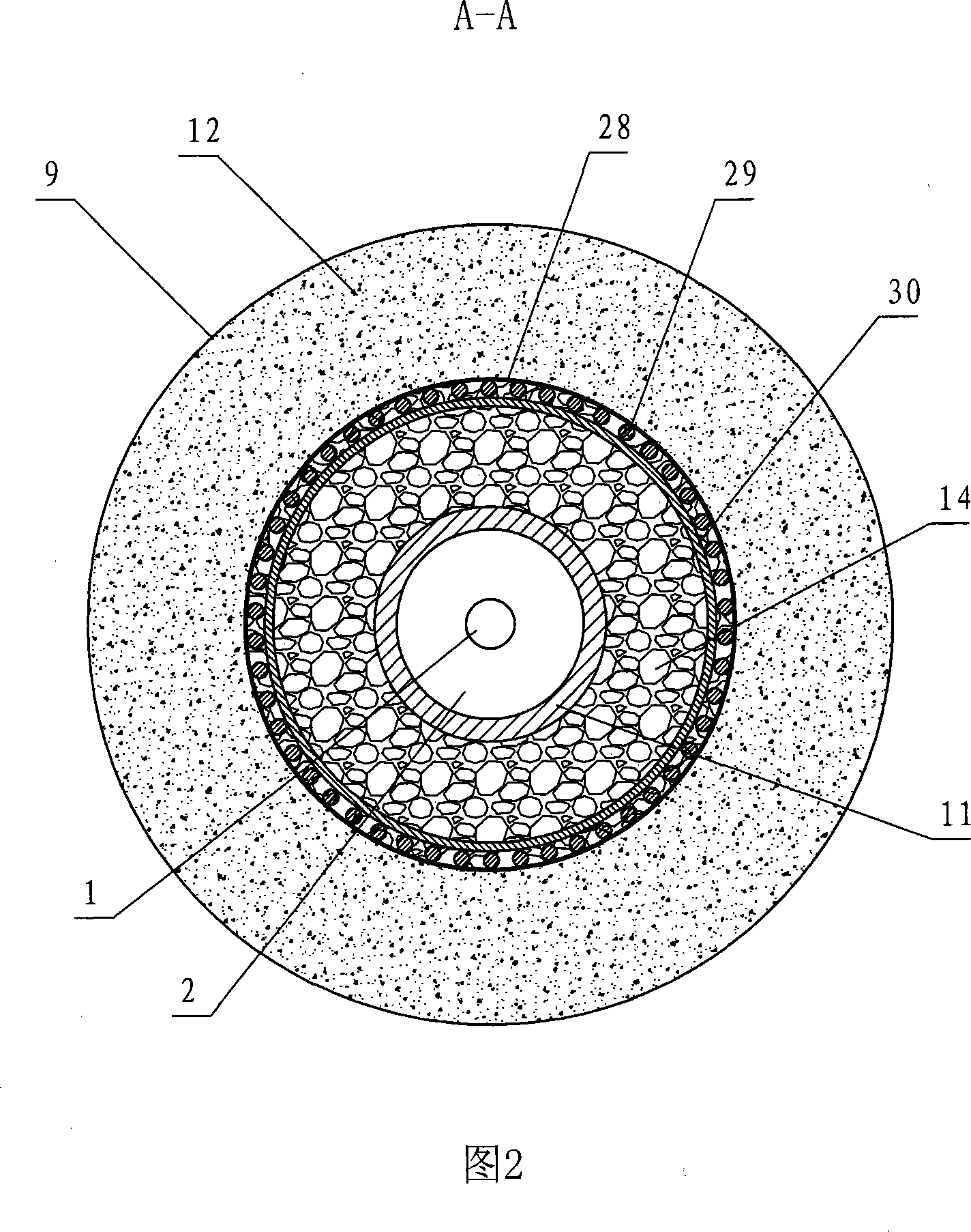
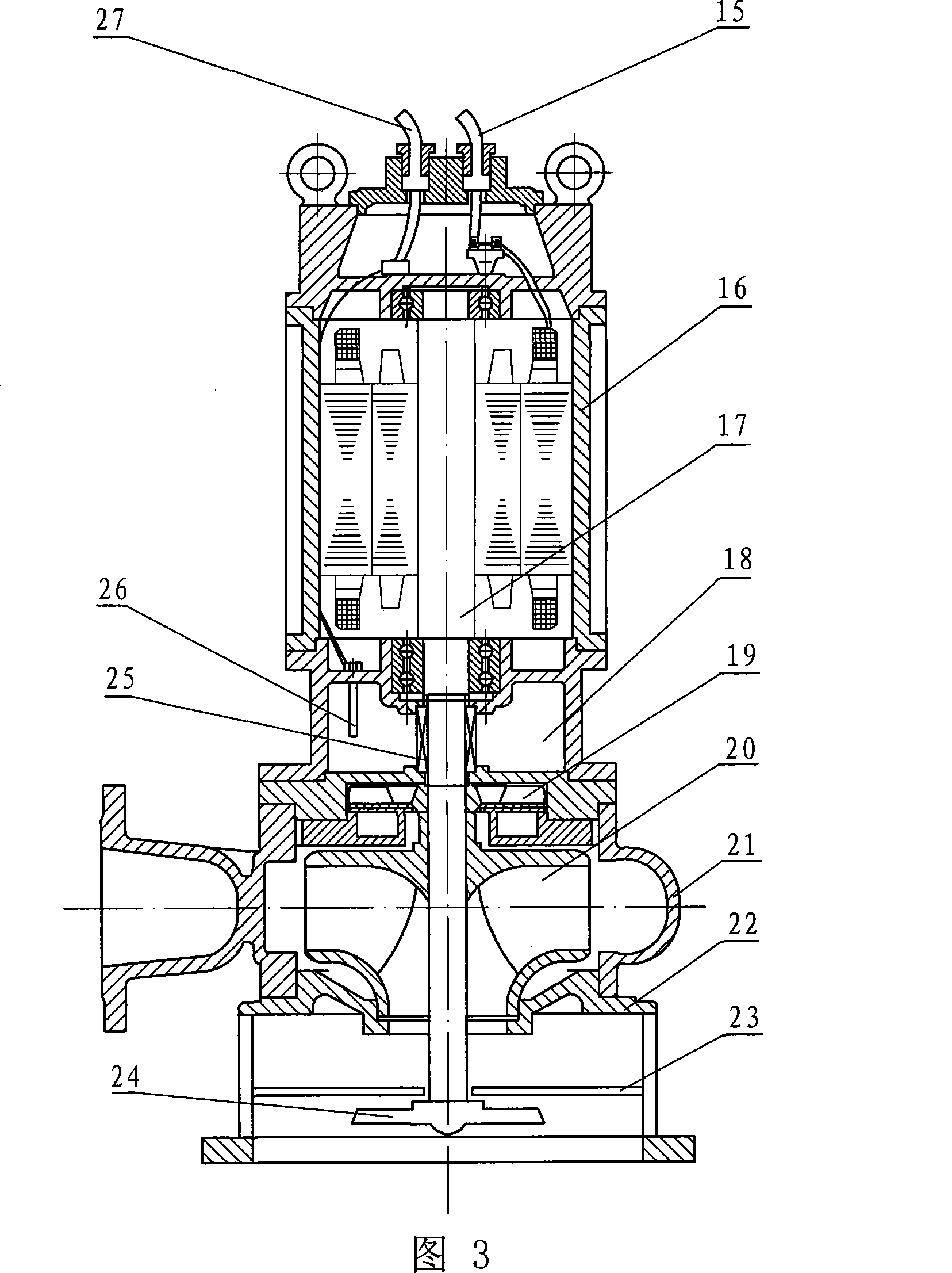
[0012] The specific structure of the present invention will be described in detail according to FIGS. 1 to 3 . The powerful anti-clogging automatic sewage discharge and wall protection type refilling device is improved on the basis of an "anti-clogging automatic sewage drainage and refilling device" designed by the inventor, and can be used according to the specifications and use requirements of the heat collector wells of the existing water source heat pump units , the device is used as the heat collecting well as the wall of a single-tube well or as the wall of the pumping well where the heat collecting well is a multi-tube well. It mainly includes the well pipe 11 and the return valve 4 in the assembled well pipe 11 connected with the heat exchanger of the water source heat pump unit and the recharge water pipe controlled by it, and the automatic control powerful sewage pump installed at the bottom of the recharge water layer in the well pipe 11 10. The outlet end of the pu...


PUM


Abstract

A strong anti-fouling automatic pollution discharge breast wall type recirculation device comprises a well pipe, a recirculation water pipe which is assembled in the well pipe, is communicated with a water source heat pump and is controlled by a backwater valve, a double channel non-clogging impeller which is integrated in a pump body arranged at the bottom of a recirculation water layer in the well pipe and consists of a master impeller and an assisted impeller and the automatic control strong sewage pump of a mixer; the outlet end of the pump body is connected with a catch basin arranged outside the well pipe. The technical points are that an interlayer decompression breast wall is arranged at the external circumference of the well pipe, and the coarse gravels are filled between the well pipe and the interlayer decompression breast wall, and the fine filling gravels are filled between the interlayer decompression breast wall and the external well pipe. The invention can fundamentally solve the problems that the sand is moved at the bottom of the pumping well of the single-pipe well or multi-pipe well and the well wall collapses to cause a dead well, etc., and further has the advantages of more reasonably designed structure and more stable and reliable running besides the advantages of the effect of completely desilting and timely recirculation, and further prolongs the service life of the heat collecting well, improves the effects of preventing the fouling and recirculation, and effectively avoids the pumping well of the single-pipe or multi-pipe well from being caused to be a dead well.

Description

technical field [0001] The invention relates to an improved anti-clogging and refilling device for water source heat pump heat collecting wells, in particular to a water source heat pump unit that is suitable for underground rock formations containing quicksand. It is a powerful anti-clogging automatic sewage discharge wall protection type recharge device that causes the well wall to collapse due to sand. It is also suitable for the retaining walls of pumping wells as multi-tube wells. Background technique [0002] Existing water-source heat pump units that use heat-collecting wells to exchange heat with groundwater are divided into single-tube wells (that is, the tasks of pumping and recharging in the same tube well) and multi-tube wells (that is, one tube well pumps water, Multiple tube well recharge). Single-pipe wells are mainly set up when another reinjection well cannot be set up due to the constraints of terrain and geological conditions. Although this can save the ...

Claims


Application Information

Patent Timeline
IPC IPC(8): F24J3/08
CPCY02E10/10
Inventor 靖洪铭靖淑媛
Owner 靖洪铭
Learn More