Electronic accelerator

A technology of electron accelerators and capacitor plates, applied in the direction of DC voltage accelerators, electrical components, accelerators, etc., can solve the problems of distance reduction, inability to meet strong currents, etc., and achieve the effect of reducing operating frequency

Active Publication Date: 2008-04-09
CGN DASHENG ELECTRON ACCELERATOR TECH
View PDF0 Cites 10 Cited by
  • Summary
  • Abstract
  • Description
  • Claims
  • Application Information

AI Technical Summary

Problems solved by technology

[0006] In the existing technology, the electron acceleration can be designed as a structure with a larger diameter at the top and a smaller diameter at the bottom. Such a structure will reduce the distance between the high-frequency electrode and the corona ring, which can increase the capacitance and reduce the frequency. Small, but because the radius of the steel cylinder at the lower part of the electron accelerator is reduced, the distance between the two high-frequency electrodes is reduced, so it cannot meet the requirements of strong current

Method used


Image

  • Electronic accelerator
  • Electronic accelerator

Examples


Embodiment Construction

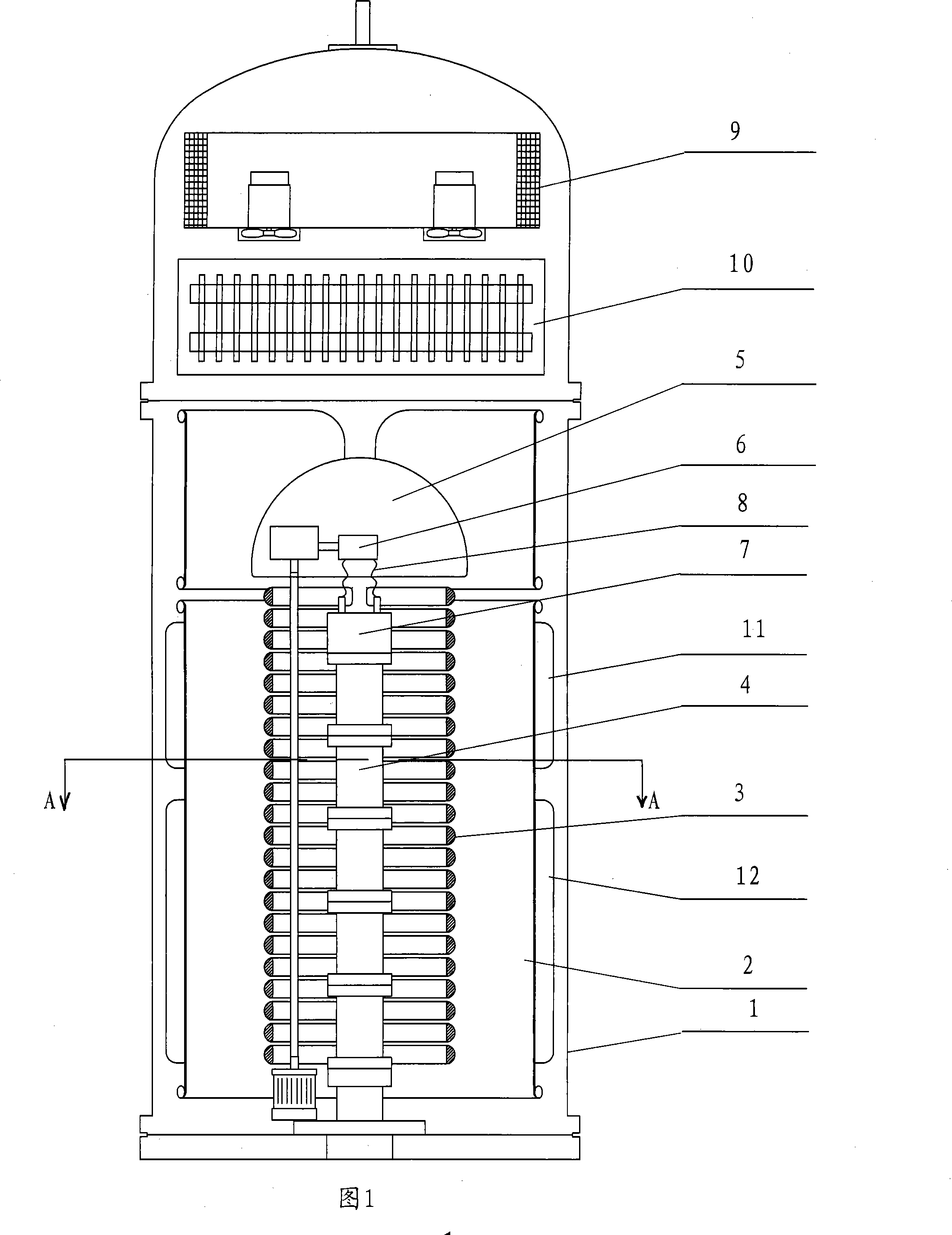
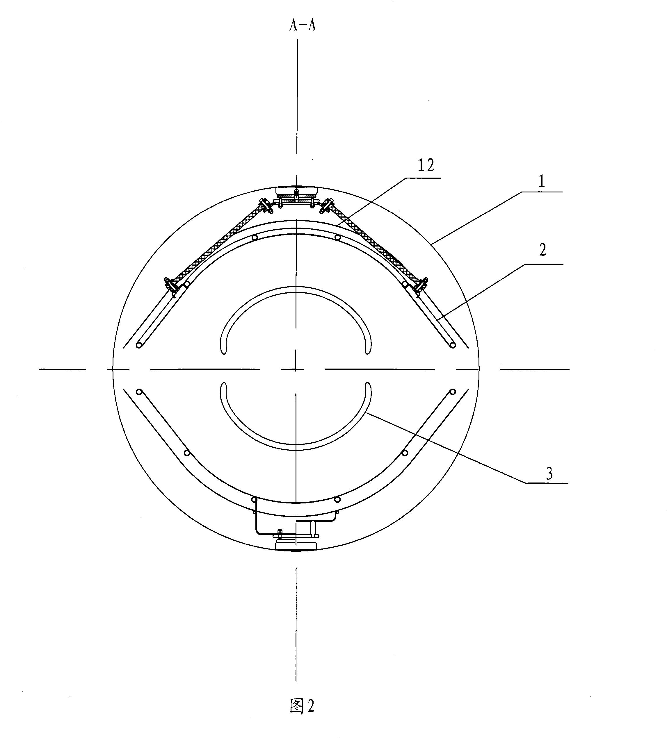
[0015] The electron accelerator shown in Figure 1 includes a steel cylinder 1, a cold trap 9 arranged above the steel cylinder 1, a high-frequency transformer 10 arranged below the cold trap 9, and a plurality of semicircular electrodes arranged inside the steel cylinder 1. Halo ring 3, a high-voltage electrode 5 arranged above the corona ring 3, two high-frequency electrodes 2 arranged outside the corona ring 3 and the high-voltage electrode 5, an electron gun 7 with a filament 8 for generating and exciting electrons, The filament transformer 6 connected with the filament 8, the vacuum accelerating tube 4 arranged under the electron gun 7, the control system arranged outside the steel cylinder 1, and the high-frequency oscillator arranged outside the steel cylinder 1 for supplying power to the electron accelerator The device, the feedback capacitance plate 11 is arranged between the steel cylinder 1 and the high-frequency electrode 1, and a plurality of semicircular corona rin...


PUM


Abstract

An electron accelerator includes a steel cylinder, a plurality of semicircular corona rings equipped inside the steel cylinder, a high voltage electrode equipped above the corona rings, two high frequency electrodes equipped outside the corona rings and the high voltage electrode, an electron gun, a vacuum accelerating tube equipped below the electron gun, a control system equipped outside the steel cylinder, a high frequency oscillator used to provide the electron accelerator with power and equipped outside the steel tube; a feedback capacitance plate equipped between the steel cylinder and the high frequency electrodes. The semicircular corona rings adopts opposite opening mode for arrangement symmetrically along the direction of the steel cylinder shaft axis. A feedback capacitance used to form high frequency oscillator electron tube triple-stage bias voltage is between the feedback capacitance plate and part of the high frequency electrodes. A compensation capacitance plate is equipped between the high frequency electrodes and the steel cylinder and can improve high frequency characteristic parameters. On the premise of no change for the distance among the high frequency electrons, the electron accelerator working frequency can be reduced and reach physical design requirements.

Description

technical field [0001] The invention relates to an electron accelerator. Background technique [0002] In the prior art, the electron accelerator is composed of the following components: a steel cylinder, a cold trap arranged on the top of the steel cylinder, a high-frequency transformer arranged on the top of the steel cylinder, a high-voltage electrode arranged below the high-frequency transformer, a core column, a Two rows of corona rings arranged on the core column symmetrically arranged on the center line of the cylinder, a silicon rectifier stack installed in the core column, two high-frequency electrodes connected with high-frequency transformers and arranged outside the two rows of corona rings, An electron gun for exciting electrons, a vacuum acceleration tube located below the electron gun, an electron gun power supply device for powering the electron gun, a filament transformer for adjusting the filament voltage of the electron gun, and a high-frequency power supp...

Claims


Application Information

Patent Timeline
Patent Type & Authority Applications(China)
IPC IPC(8): H05H5/00H05H7/00
Inventor 高文照陆洁平
Owner CGN DASHENG ELECTRON ACCELERATOR TECH
Why Eureka
Try Eureka