
Bidirectional compression hydraulic press intelligent hydraulic control system

A hydraulic control system and two-way pressing technology, applied in the field of hydraulic presses, can solve the problems of unstable system pressure, inability to meet, low work efficiency, etc., and achieve the effects of reducing manufacturing costs, reasonable structure design, and high work efficiency

Inactive Publication Date: 2008-04-23
TIANJIN TIANDUAN PRESS CO LTD
View PDF0 Cites 13 Cited by
  • Summary
  • Abstract
  • Description
  • Claims
  • Application Information

AI Technical Summary

Problems solved by technology

[0002] At present, there are many ways to apply pressure to the powdery material to form it. The more advanced one is to use the two-way press forming technology of the hydraulic press. In the existing two-way press hydraulic press hydraulic control system, the upper master cylinder and the lower master cylinder are used The spool valve structure makes the upper master cylinder and the lower master cylinder of the hydraulic machine not have the function of communicating and maintaining pressure. Since the pressing pressure of the upper master cylinder and the lower master cylinder is not equal, the powder in the mold is under different pressure, and the pressing density of the pressed product is different. It is difficult to maintain uniformity; since the control valve group in the hydraulic control system only has a relief valve with one pressure value, when the high-pressure relief valve is used to adjust the low pressure of the upper master cylinder or the lower master cylinder, it will be caused by the characteristics of the valve The pressure of the system is unstable, which cannot meet the requirements of different pressing processes and different mold changes, which directly affects the quality of the pressed products; in order to achieve the accelerated operation of the upper and lower sliders of the hydraulic press, some pump structures need to be added to the hydraulic control system. This leads to the overall hydraulic control system is not only huge but also complex in structure, increases the manufacturing cost of the hydraulic press, and also brings many difficulties to installation and maintenance; because the above-mentioned hydraulic control system has a single function, it cannot meet the needs of different pressing processes and various mold changes. Requirements, so it leads to low work efficiency and poor stability, which directly affects the quality of processed products

Method used


Image

  • Bidirectional compression hydraulic press intelligent hydraulic control system

Examples


Embodiment Construction

[0018] In order to further understand the invention content, characteristics and effects of the present invention, the following examples are given, and detailed descriptions are as follows in conjunction with the accompanying drawings:

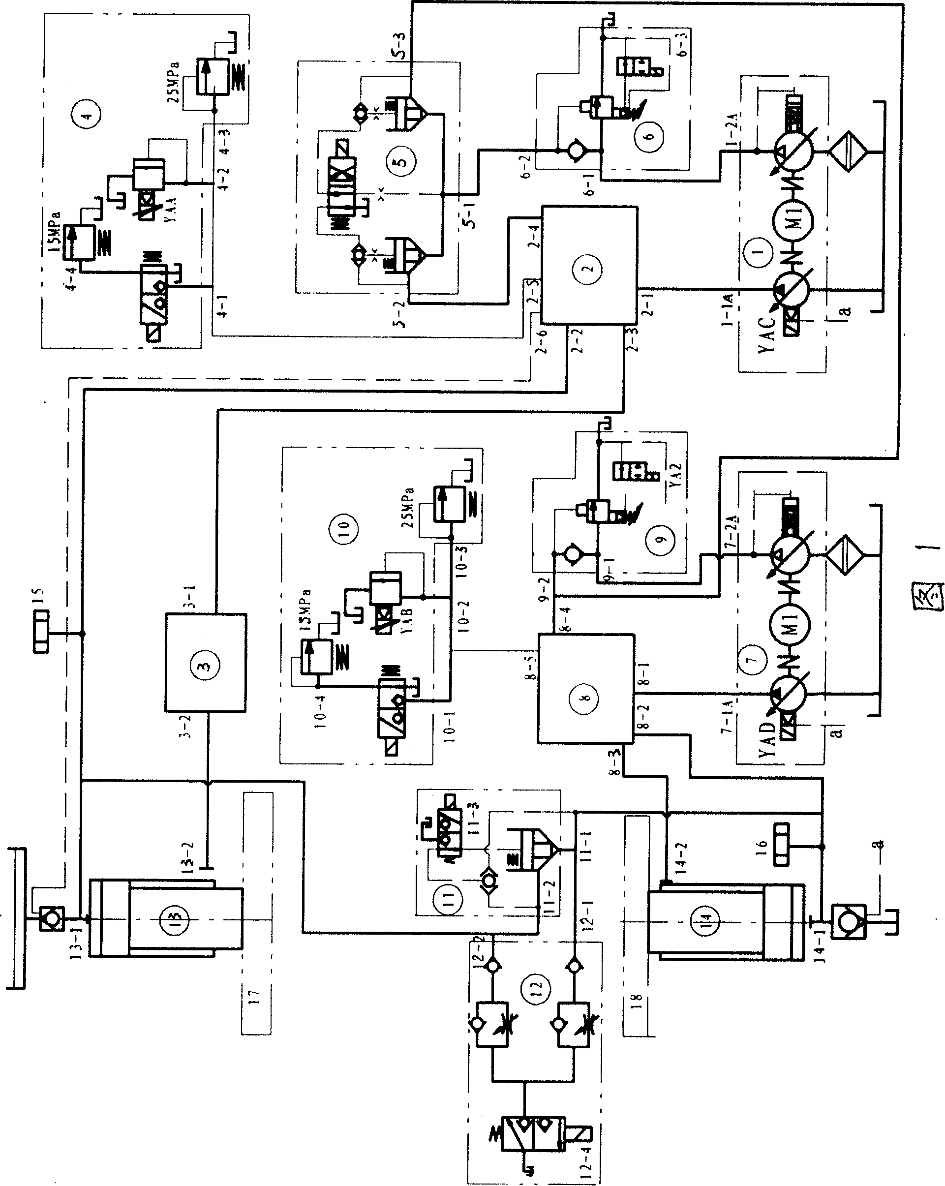
[0019] Please refer to Fig. 1, the intelligent hydraulic control system of the two-way pressing hydraulic machine, including the upper master cylinder 13, the lower master cylinder 14, valve group, oil circuit, oil pump and oil tank, the valve group includes the upper master cylinder proportional pump group 1, the upper master cylinder Pump outlet valve group 2, support valve group 3, upper master cylinder control valve group 4, conversion valve group 5, upper master cylinder unloading valve group 6, lower master cylinder proportional pump group 7, lower master cylinder pump outlet valve group 8, The lower master cylinder unloading valve group 9, the lower master cylinder control valve group 10, the connecting valve group 11 and the unloading ...


PUM


Abstract

The present invention relates to a bidirectional pressing hydraulic machine intelligent hydraulic control system. Said system includes upper main cylinder, lower main cylinder, valve group, oil line, oil pump and oil tank. The described valve group includes upper and lower main cylinder proportion pump group, upper and lower main cylinder pump outlet valve group, supporting valve group, upper and lower main cylinder control valve group, conversion valve group, upper and lower main cylinder unloading valve group, communication valve group and unloading valve group.

Description

technical field [0001] The invention belongs to the technical field of hydraulic presses, and in particular relates to an intelligent hydraulic control system for bidirectional press hydraulic presses. Background technique [0002] At present, there are many ways to apply pressure to the powdery material to form it. The more advanced one is to use the two-way press forming technology of the hydraulic press. In the existing two-way press hydraulic press hydraulic control system, the upper master cylinder and the lower master cylinder are used The spool valve structure makes the upper master cylinder and the lower master cylinder of the hydraulic machine not have the function of communicating and maintaining pressure. Since the pressing pressure of the upper master cylinder and the lower master cylinder is not equal, the powder in the mold is under different pressure, and the pressing density of the pressed product is different. It is difficult to maintain uniformity; since th...

Claims


Application Information

Patent Timeline
IPC IPC(8): B30B15/16
Inventor 杨丽华
Owner TIANJIN TIANDUAN PRESS CO LTD
Learn More