Current limiting short circuit protection circuit

A short-circuit protection circuit and current-limiting technology, applied in emergency protection circuit devices, protections that respond to overcurrent, electrical components, etc. Efficiency, reduced design cost, and fast response

Active Publication Date: 2008-04-23
ANYKA (GUANGZHOU) MICROELECTRONICS TECH CO LTD
View PDF0 Cites 27 Cited by
  • Summary
  • Abstract
  • Description
  • Claims
  • Application Information

AI Technical Summary

Problems solved by technology

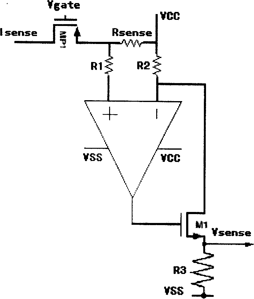
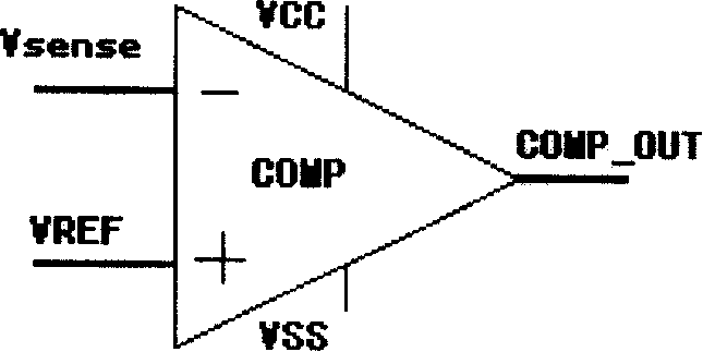
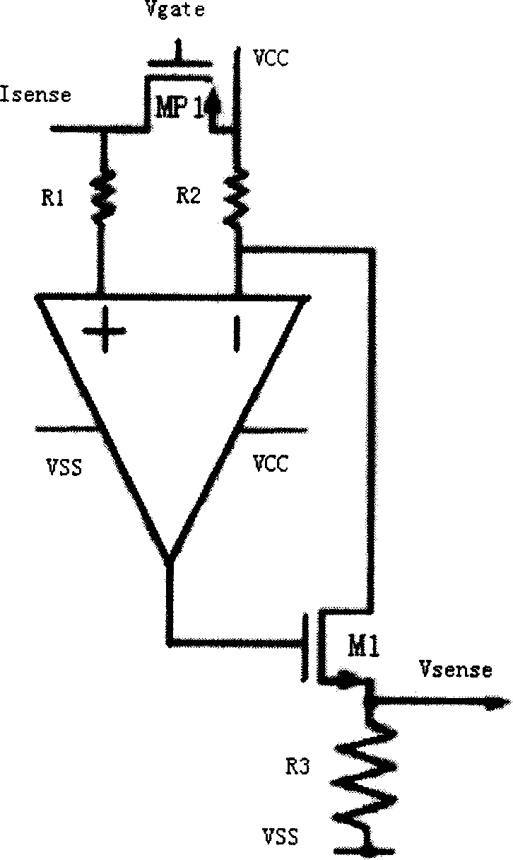
Because such a solution needs an amplifier, a hysteresis comparator, and a reference voltage VREF, the circuit is generally complicated, and the power consumption is generally too large to greatly reduce the current efficiency; and when the circuit (such as LDO, Charger, etc.) is working normally, the current limit The / short circuit protection circuit is always in the working state of continuous detection and comparison, which greatly wastes power consumption, especially when the load current of the circuit (such as LDO) is 0 or the load current is small, this excessive power consumption will greatly reduce the system. efficiency
The A solution requires an externally integrated precision resistor, which increases the system cost and reduces the system efficiency.

Method used


Image

  • Current limiting short circuit protection circuit
  • Current limiting short circuit protection circuit
  • Current limiting short circuit protection circuit

Examples


Embodiment Construction

[0040] As shown in FIG. 5 , it is a circuit diagram of an embodiment of the current-limiting short-circuit protection circuit of the present invention. The current-limiting short-circuit protection circuit adopts the current mirror equal ratio mirror bias current Ibias composed of the tube FET M0, the FET M1 and the FET M2; the width-to-length ratio of the low-power tube MP2 and the high-power tube MP1 is 1: N; the mirror image ratio of FET M3 and FET M4 is K; resistor R3 is a 100-ohm polysilicon (poly) resistor; VCC and VSS are input voltage and analog ground respectively, Vo is the output terminal, and Io is current load.

[0041] FET M0, FET M1, and FET M2 are composed of a current mirror equal-proportional mirror circuit. The sources of FET M0, FET M1, and FET M2 are all connected to the ground. FET M1, The drain of the field effect transistor M2 is connected to the drains of the field effect transistor M3 and the field effect transistor M4 respectively, and the field eff...


PUM


Abstract

This invention discloses a protection circuit of limit short circuit including field effect transistors M0, M1, M2, M3, M4, power valves MP1 and MP2 and resistor R3, in which, a current mirror made up of M0, M1 and M2 is in the equal proportion to an image circuit and the sources of M0, M1 and M2 are connected to the earth, the drains of M1 and M2 are connected with the drains of M3 and M4, and M3 and M4 form the image circuit, one end of R3 is connected with the sources of M3 and MP1, the other end is connected with the sources of M4 and MP2.

Description

technical field [0001] The invention mainly relates to the field of power management integrated circuits, in particular to a current-limiting short-circuit protection circuit suitable for power management integrated circuits. Background technique [0002] At present, portable electronic devices (such as mobile phones, PDAs, MP3s, etc.) are mainly powered by lithium batteries through a low-dropout linear voltage regulator (LDO) and a switching DC regulator (DCDC). Power tubes are used in these power converters. The quality index of the power converter should be based on safety and reliability as the first principle. However, when DC-DC, LDO and other power management chips are used, the output terminals may be short-circuited due to application errors or other accidents, which will generate a large current, which is enough to burn the chip. Therefore, under the condition that the electrical technical indicators meet the normal use requirements, in order to make the power su...

Claims


Application Information

Patent Timeline
Patent Type & Authority Applications(China)
IPC IPC(8): H02H3/08H02H7/10
Inventor 刘坚斌刘军余佳
Owner ANYKA (GUANGZHOU) MICROELECTRONICS TECH CO LTD
Why Eureka
Try Eureka