Liquid-cooling heat radiator

A cooling device and liquid cooling technology, applied in cooling/ventilation/heating transformation, instrument cooling, instrument and other directions, can solve the problems of reducing cooling effect, reducing heat dissipation efficiency, increasing wind resistance, etc., to improve cooling and cooling capacity, increase heat dissipation area, the effect of improving heat dissipation efficiency

Inactive Publication Date: 2008-04-23
INVENTEC CORP
View PDF0 Cites 26 Cited by
  • Summary
  • Abstract
  • Description
  • Claims
  • Application Information

AI Technical Summary

Problems solved by technology

[0004] Since the working fluid flows in the liquid inlet pipe 36a, it is cooled by means of the heat dissipation fan device 20a and the heat exchanger 39a. When the temperature is reduced, the temperature drop time of the working fluid will be reduced, thereby reducing the heat dissipation efficiency
[0005] Furthermore, when the above-mentioned cooling fan unit 20a generates wind force to cool the liquid inlet pipe 36a, the airflow enters and exits along the axial direction of the cooling fan un

Method used


Image

  • Liquid-cooling heat radiator
  • Liquid-cooling heat radiator
  • Liquid-cooling heat radiator

Examples


Embodiment Construction

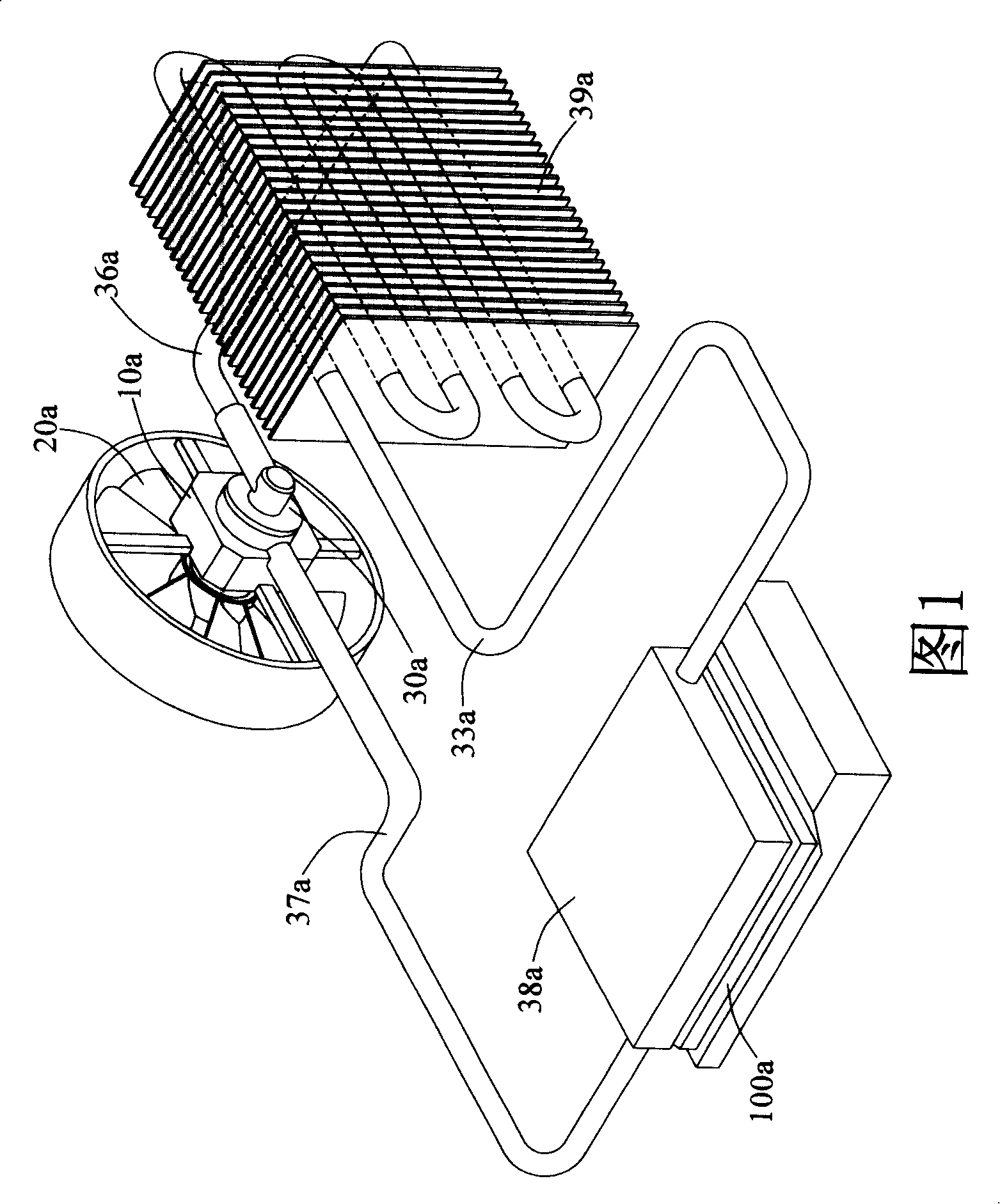
[0068] The liquid-cooled heat dissipation device disclosed in the present invention is applied to heat-generating electronic components, wherein the heat-generating electronic components are central processing unit chips, but are not limited to central processing unit chips, such as integrated circuit chips that can generate heat. In the following specific embodiments of the present invention, the technology disclosed in the invention will use a central processing unit chip as an application embodiment.

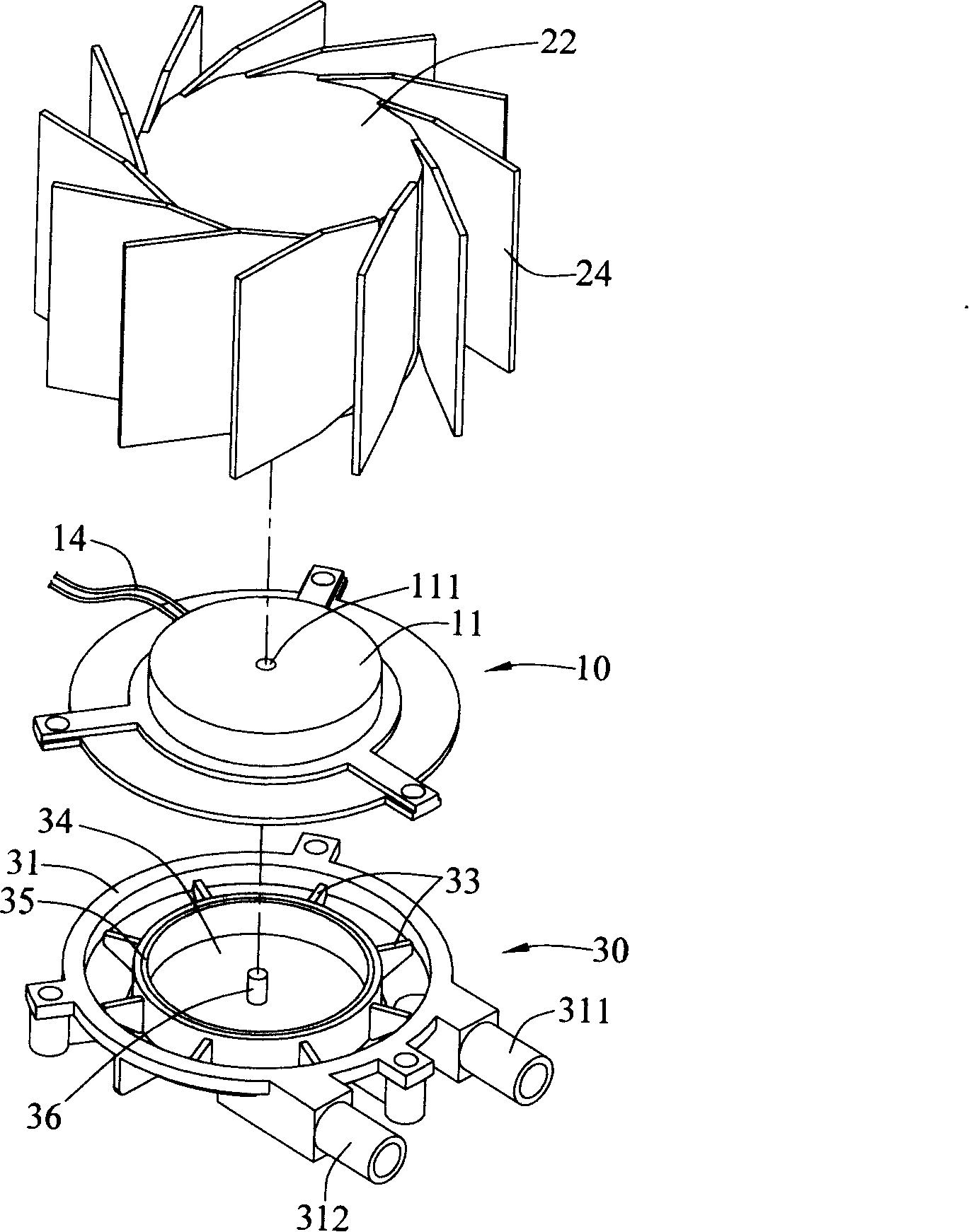
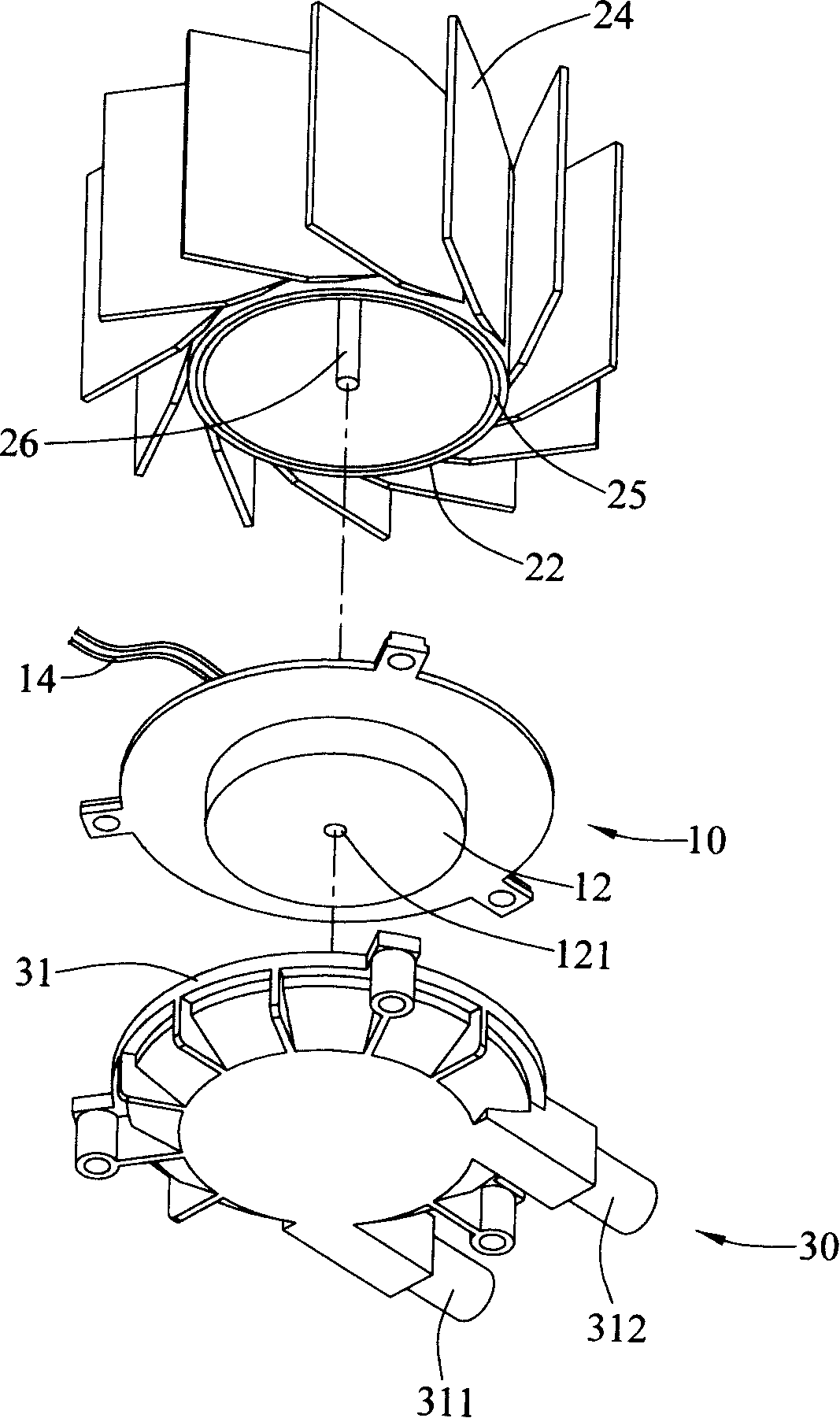
[0069] Please refer to Figure 2A , Figure 2B, and with reference to FIG. 3 , it includes a motor 10, a cooling fan 20, a pump 30 and a liquid pipe 50, wherein the motor 10 and the pump 30 are located in the housing 40, and the housing 40 is provided with two through holes 41, 42, and the motor The first stator 11 and the second stator 12 protrude from the two sides of 10 respectively, and the top side of the first stator 11 and the bottom side of the second stator 12 each h...


PUM


Abstract

Carrying out heat exchange with heat source, the disclosed liquid cooling type heat sink includes a fan for heat elimination, a pump, a fluid tube, a motor, and a heat elimination block. The motor is in use for driving the fan for heat elimination and the pump. Two ends of fluid tube are connected to the pump to form loop of fluid. The fluid tube is contacted to the heat elimination block, which is setup on the heat source. Being positioned at the path of out air, a curvature of fluid tube is formed on section, where the heat elimination block is left from the fluid tube. The fan for heat elimination cools the said curvature of fluid tube by wind power, increases speed for dropping temperature, and raises efficiency of heat elimination of the fluid tube.

Description

technical field [0001] The invention relates to a liquid-cooled heat dissipation device, in particular to a heat dissipation device capable of improving the cooling capacity of a liquid pipe. Background technique [0002] Electronic components such as central processing unit chips and power integrated circuits in computer equipment will generate heat when performing calculations, and the operating temperature will increase accordingly. Since the operating temperature has a great impact on the normal operation of computer equipment, in order to reduce the heat generation of electronic components The working temperature of the components and maintain effective operation, through the heat dissipation design to design a variety of heat dissipation devices, such as liquid-cooled heat dissipation device is one of them, this liquid-cooled heat dissipation device includes a radiator, cooling circulation device and fan, so The cooling circulation device must be equipped with a motor ...

Claims


Application Information

Patent Timeline
IPC IPC(8): H05K7/20H01L23/473G06F1/20G12B15/00
Inventor 陈文华
Owner INVENTEC CORP
Why Eureka
Try Eureka