
Groove tooth-shape structure for drafting lower roller

A groove and tooth shape technology, applied in drafting equipment, textiles, papermaking, spinning machines, etc., can solve the problem of affecting the uniformity of the evenness and the quality of the finished product, reducing the contact area between the working surface of the groove and the top roller, Affects the uniformity of evenness and finished product quality, and achieves the effect of improving yarn holding force, reducing processing procedures and reducing mechanical waves

Inactive Publication Date: 2008-04-30
常州市同和纺织机械制造有限公司
View PDF0 Cites 4 Cited by
  • Summary
  • Abstract
  • Description
  • Claims
  • Application Information

AI Technical Summary

Problems solved by technology

At present, the groove tooth shape of the drafting bottom roller disclosed is trapezoidal or arc-shaped. Since the long diameter of the drafting bottom roller is relatively large, the roller will be deformed during the rolling, straightening, heat treatment and other processing processes of the drafting roller. , making the radial runout of the roller difficult to control
For the trapezoidal tooth, after the cylindrical grinding of the bottom roller, the width of the top of the tooth is not easy to keep consistent, because the transition between the top of the tooth and its two sides is a sudden transition, and because of the obtuse angle of the working surface of the groove, the wear of the top roller will be accelerated. Moreover, mechanical waves will be generated during the spinning process, which will affect the uniformity of the evenness and the quality of the finished product.
As for arc-shaped teeth, although the working surface of the groove is an arc transition, but because the outer circle of the roller is only the highest point of the working surface of the groove, the contact area between the working surface of the groove and the top roller is reduced, and at the same time it increases Changes in the gripping force of the yarn at the nip will also affect the uniformity of the evenness and the quality of the finished product

Method used


Image

  • Groove tooth-shape structure for drafting lower roller
  • Groove tooth-shape structure for drafting lower roller

Examples


Embodiment Construction

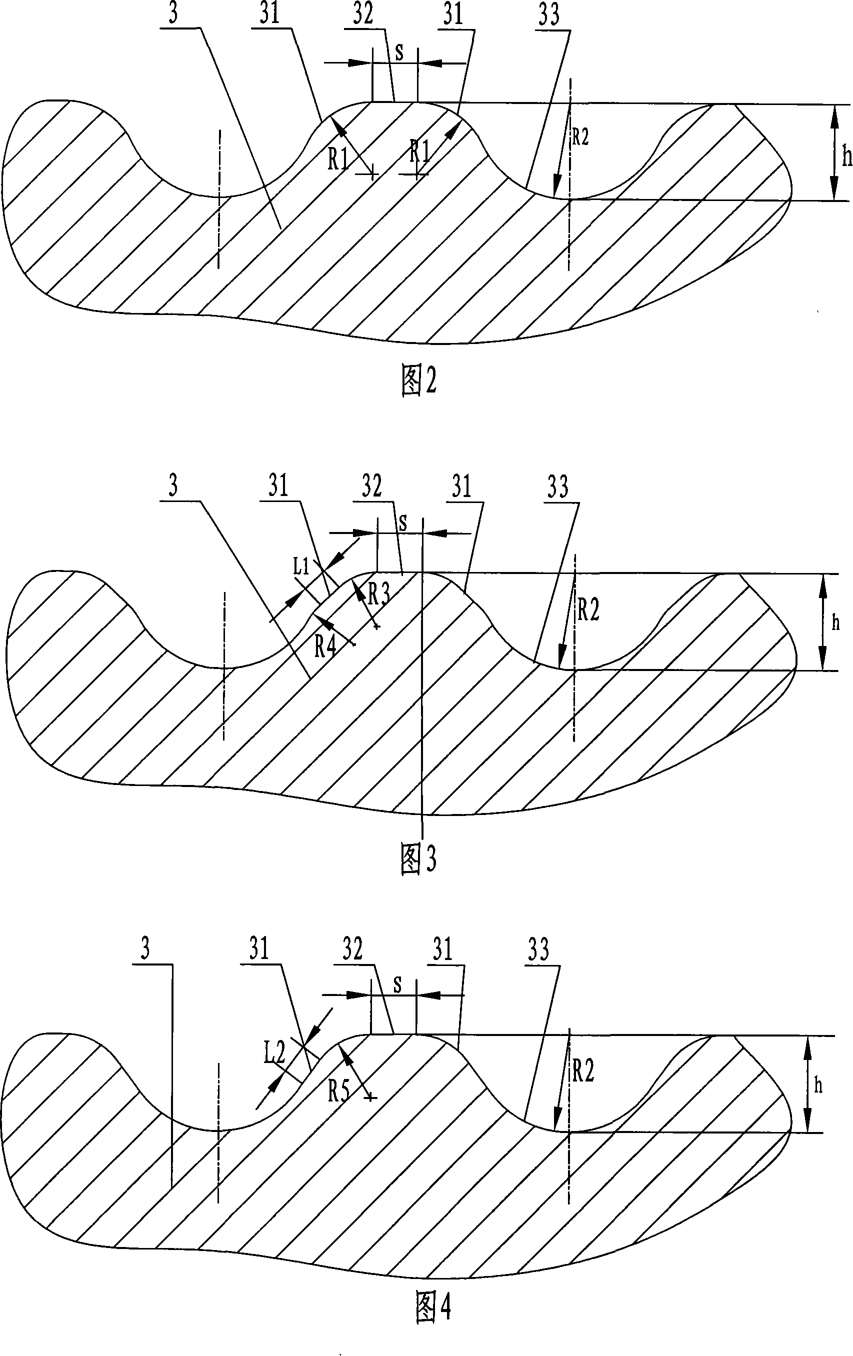
[0016] The groove tooth structure of the drafting bottom roller of the present invention is shown in Fig. 1, and the drafting bottom roller includes an optical axis 1, a groove working surface 2 and a guide hole arranged at intervals between the optical axes 1, and the groove The groove tooth profile 3 on the working surface 2 can be a helical tooth profile or a straight tooth profile. The groove tooth shape 3 is shown in Figure 2, and its outer contour is composed of the addendum arc length 31 formed by the outer circle of the roller, the curve 32 smoothly transitioned to the two ends of the addendum arc length 31, and the tooth tangent to the curve 32. Bottom arc length 33, the curve 32 is the transition arc length inscribed with the addendum arc length 31, and the radius R2 of the tooth bottom arc length 33 ≥ the radius R1 of the excess arc length, the chord length S of the addendum arc length is 0.1mm~0.5mm, the radius R1 of the transition arc length is 0.25mm~0.4mm, the r...


PUM

PropertyMeasurementUnit
Chord lengthaaaaaaaaaa

Abstract

The invention relates to a flute tooth shape structure of a drafting bottom roller, which belongs to the textile machinery technical field. The flute tooth shape is formed by rolling depression and roll milling, the outline of a flute tooth-shaped cross section comprises a tooth top arc length formed by a roller external circle, a curved line smoothly and transitionally connected with the tooth top arc length, and a tooth bottom arc length tangent with curved line. The flute tooth shape of the drafting bottom roller of the invention has a smooth and transitional flute working surface, improves the wear condition of a leather roller, prolongs the service life of a leather roller, increases the contact area of the leather roller and the flute working surface of the roller, and enhances the gripping force to yarn, the change of the gripping force of the flute working surface and the roller is more uniform, a mechanical wave in the spinning process is reduced, and the spinning quality is greatly improved.

Description

technical field [0001] The invention relates to a drafting assembly of a textile machine, in particular to a groove tooth structure of a drafting bottom roller, which belongs to the technical field of textile machines. Background technique [0002] The drafting bottom roller of the spinning machine is composed of optical axes, grooved working surfaces and guide holes arranged at intervals between the optical axes, and is one of the very important parts in the spinning machine. The grooved working surface on the drafting bottom roller and the top roller corresponding to the top roller form a jaw to hold the yarn for drafting. The mechanical wave generated by the roller in the spinning process is closely related to the tooth shape of the working surface of the drafting bottom roller. At present, the groove tooth shape of the drafting bottom roller disclosed is trapezoidal or arc-shaped. Since the long diameter of the drafting bottom roller is relatively large, the roller will...

Claims


Application Information

Patent Timeline
IPC IPC(8): D01H5/78
Inventor 崔桂生
Owner 常州市同和纺织机械制造有限公司
Learn More