Self-suction gas-liquid mixing impeller

A gas-liquid mixing and self-priming technology, which is applied in the direction of mixers, mixing methods, fluid mixers, etc., can solve the problems of poor gas-liquid mixing and dispersion, inability to increase air suction and suction and discharge at the same time, equipment vibration, etc. The problem is to achieve the effect of convenient adjustment of the air-bleeding volume, good air-water mixing effect, and increasing the length of the flow channel

Active Publication Date: 2008-05-07
CHINA PETROLEUM & CHEM CORP +1
View PDF29 Cites 25 Cited by
  • Summary
  • Abstract
  • Description
  • Claims
  • Application Information

AI Technical Summary

Problems solved by technology

The disclosed impellers of US5091083, US5242600, US3414245, etc. include a plurality of hollow blades, and the air distribution holes are arranged on the rear side of the top of the blades. It utilizes the vacuum vortex generated on the rear side of the blades when the impeller rotates to introduce air into the impeller and release it into the water through the air distribution holes. ; This kind of impeller has low vacuum degree, small air suction capacity, and no suction and drainage capacity. It only depends on the agitation of the impeller to disperse the air bubbles, and the gas-liquid mixing and dispersion effect is poor; Enter the vacuum vortex and accumulate on the exhaust hole
The disclosed impellers of US6270061, US4297214, US2246560, US2238139, etc. are composed of upper and lower cover plates and guide vanes in the middle. The upper cover plate is provided with a water inlet, and the air inlet is located at the center of the impeller; The negative pressure area generated at the place sucks in air, and mixes it with water inside

Method used


Image

  • Self-suction gas-liquid mixing impeller
  • Self-suction gas-liquid mixing impeller
  • Self-suction gas-liquid mixing impeller

Examples


Embodiment Construction

[0032] The structure and operation mode of the present invention will be further described below in conjunction with the accompanying drawings.

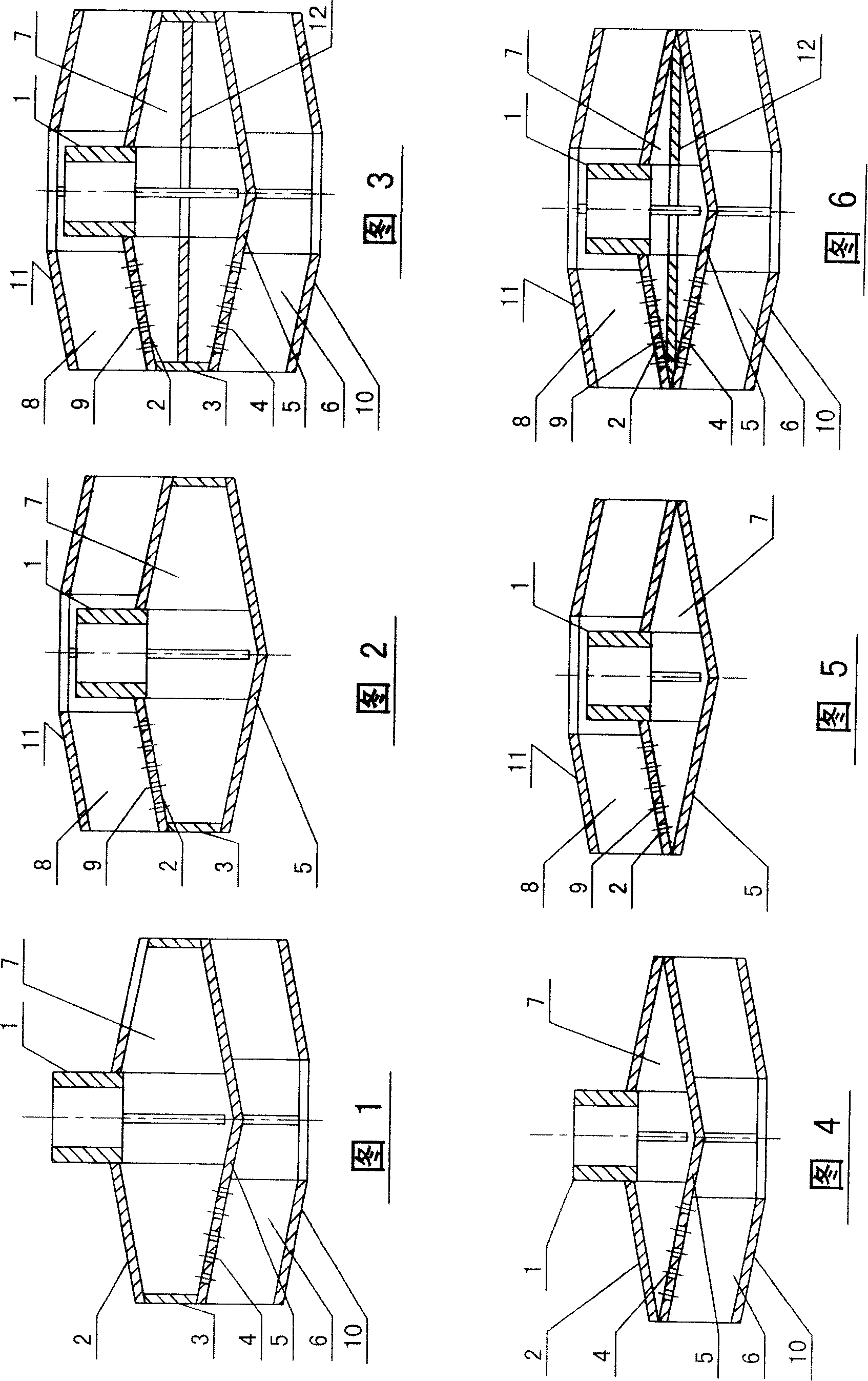
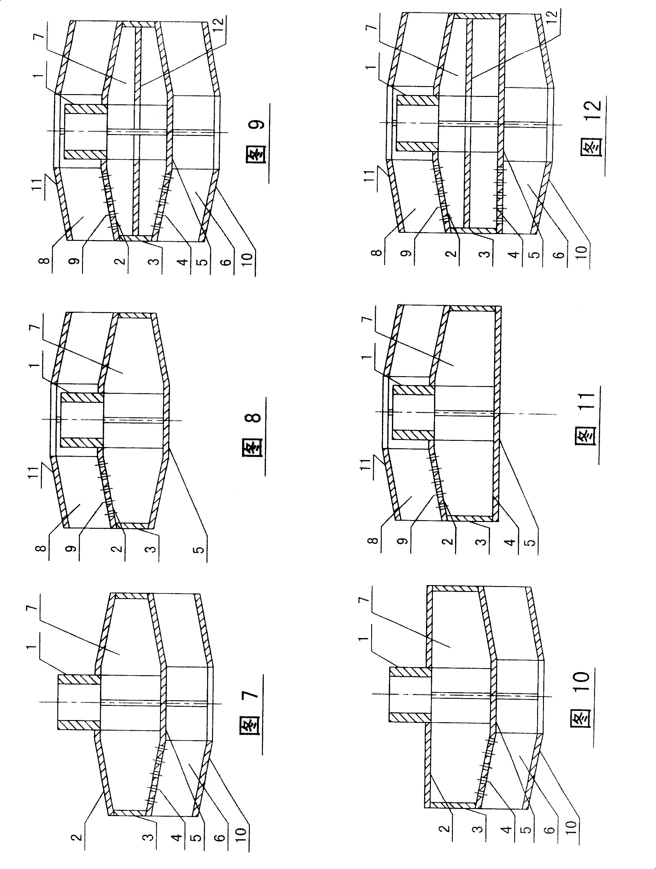
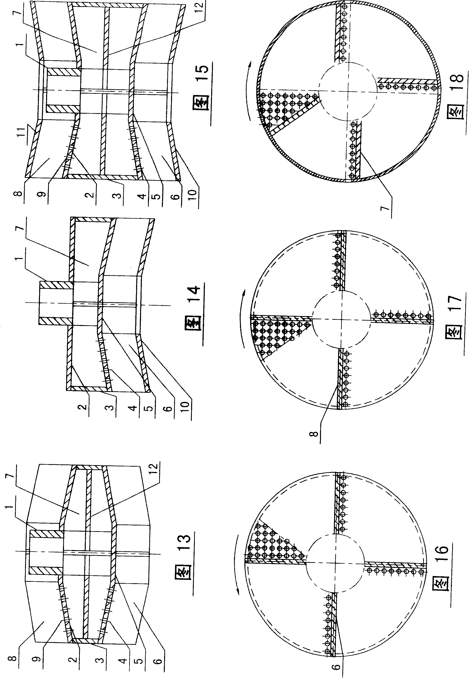
[0033] As shown in Figures 1 to 15, the self-entrained gas-liquid mixing impeller of the present invention consists of a hollow coupling 1, an upper cover plate 2, a cylinder 3 (the cylinder 3 may not be provided, as shown in Figures 5 and 6), The lower cover plate 5, the lower guide vane 6 and / or the upper guide vane 8, wherein the upper cover plate 2, the cylinder body 3, and the lower cover plate 5 constitute the cylindrical hollow disk of the impeller; the lower guide vane 6 and the lower guide vane The air distribution holes 4 of the cover plate are arranged on the lower cover plate 5, and the air distribution holes 4 of the lower cover plate are located on the rear side of the lower guide vane 6; the upper guide vanes 8 and the air distribution holes 9 of the upper cover plate are arranged on the upper cover plate 2, and the upp...


PUM


Abstract

The invention relates to a self-suction gas-liquid mixing impeller, which mainly consists of a shaft joint, a hollow disk, and guide vanes. Both the top plate and the bottom plate of the hollow disk can be provided with guide vanes; Structures with varying thickness. The impeller of the present invention can inhale gas through the negative pressure generated during the rotation process, and disperse the gas into the liquid in the form of micro-bubbles. It has the characteristics of large suction volume, good gas-liquid mixing effect, low energy consumption, and no clogging of the impeller, and is widely used. It is used in the fields of gas-liquid mixing and reaction, and phase separation, and forms a variety of special equipment, such as wastewater biochemical treatment equipment, air flotation equipment, waste gas purification equipment, and gas purification equipment in the fields of chemical industry, pharmaceuticals, metallurgy, food, papermaking, etc. Liquid contact and reaction equipment, etc.

Description

technical field [0001] The invention relates to a gas-liquid mixing device, in particular to a self-suction gas-liquid mixing impeller. Background technique [0002] The self-priming gas-liquid mixing impeller uses the negative pressure generated during the high-speed rotation of the impeller in the liquid to guide air or other gases from the hollow shaft driving the impeller or the sleeve outside the shaft to the impeller, and the gas is passed through the impeller. Disperses in the liquid in the form of microbubbles. It can be used in the field of chemical reaction between gas and liquid to improve mass transfer efficiency and simplify equipment structure; it can also be used in liquid-liquid separation and liquid-solid separation and other phase separation fields, such as removing solids, oil, fibers and other pollutants in sewage , can make pollutants adhere to the micro-bubbles, and rise to the water surface with the micro-bubbles, so as to achieve the purpose of pollu...

Claims


Application Information

Patent Timeline
IPC IPC(8): B01F5/16B01F3/04B01F17/02B03D1/16C02F1/24C02F3/20B01F25/64C09K23/02
CPCY02W10/10
Inventor 回军韩建华赵景霞许谦杨丽
Owner CHINA PETROLEUM & CHEM CORP
Why Eureka
Try Eureka