
Particle analyzer of sheath-flow impedance method

A particle analyzer and impedance method technology, used in individual particle analysis, particle and sedimentation analysis, and analysis of materials, etc., can solve the problems of high driving pressure of the back sheath flow, liquid consumption, and difficulty in signal identification, so as to avoid the shunt effect, Guaranteed effectiveness and noise isolation effect

Active Publication Date: 2008-05-07
SHENZHEN MINDRAY BIO MEDICAL ELECTRONICS CO LTD +1
View PDF7 Cites 32 Cited by
  • Summary
  • Abstract
  • Description
  • Claims
  • Application Information

AI Technical Summary

Problems solved by technology

However, in this way, the liquid path from the sheath fluid storage tank to the counting tank will inevitably act as a conductive line, which will inevitably introduce electromagnetic interference signals into the counting tank, and this signal will be superimposed on the impedance of the small hole. signal, thus making signal identification difficult
In order to reduce interference, long and thin capillary glass tubes must be selected, which increases the application risk; at the same time, in order to reduce interference, it is also necessary to avoid the use of small, sensitive solenoid valves to control the liquid circuit, so as to increase the risk of the liquid circuit. The design is troublesome; moreover, the driving pressure of the back sheath flow in this method is high, resulting in a large consumption of fluid
[0005] U.S. Patent No. 5,905,214 is driven by the method of "positive pressure drive". The power to push the rear sheath fluid into the rear pool comes from the positive pressure in the upstream pool. To ensure that the positive pressure can be transmitted to the rear pool, it is necessary to ensure that the fluid along the way The sealing of the road and the continuous supply of liquid, so it is difficult to ensure that no external interference signals are introduced into the rear pool
U.S. Patent US 6,909,269 uses the method of placing the counting cell in a special shielding box, which has a certain shielding effect, but it cannot prevent the backflow of the sample after entering the back cell and generate false signals

Method used


Image

  • Particle analyzer of sheath-flow impedance method
  • Particle analyzer of sheath-flow impedance method
  • Particle analyzer of sheath-flow impedance method

Examples


Embodiment Construction

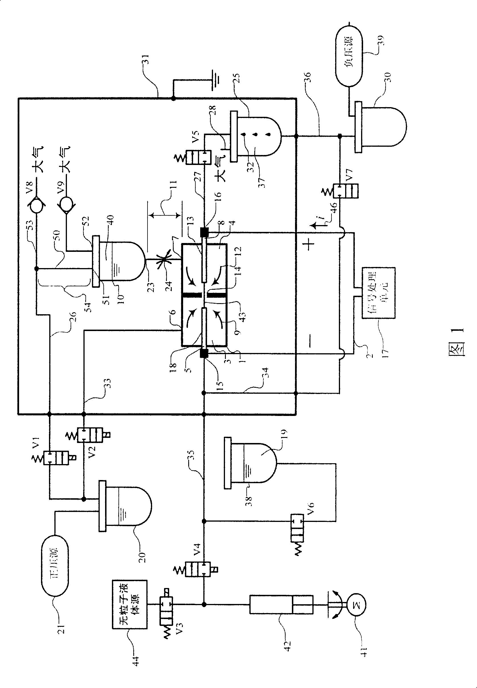
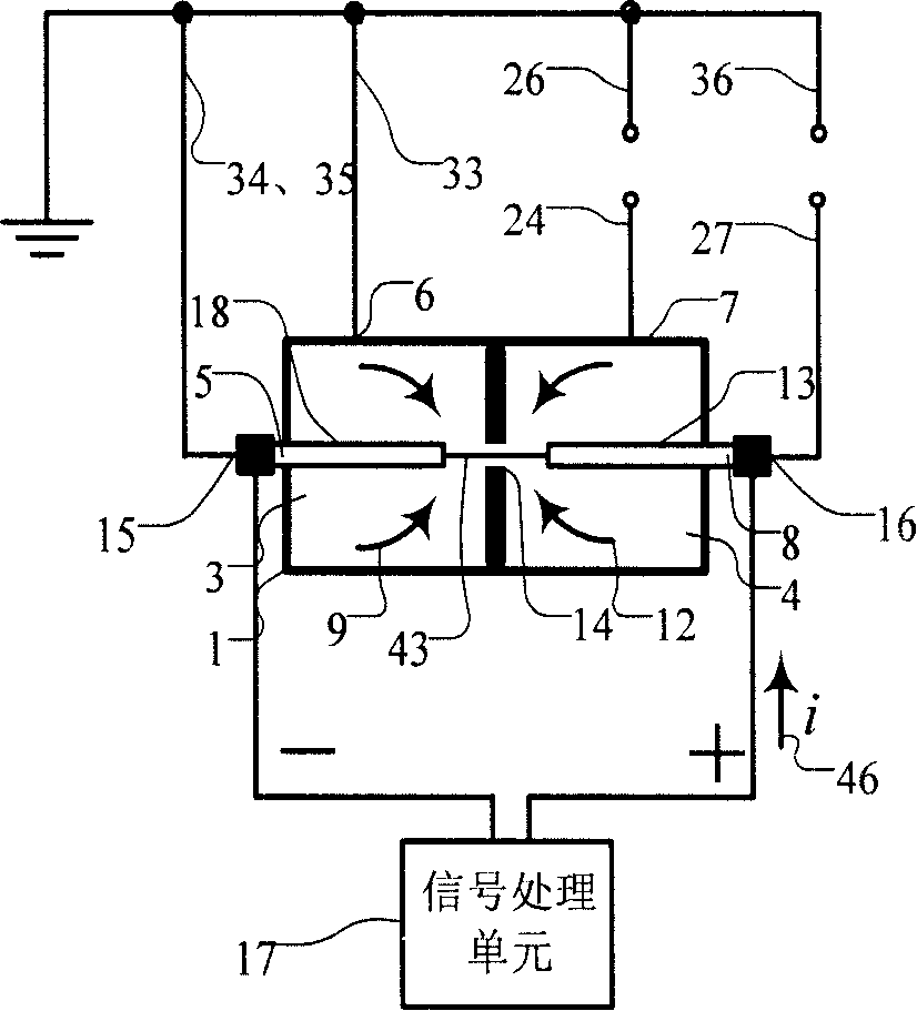
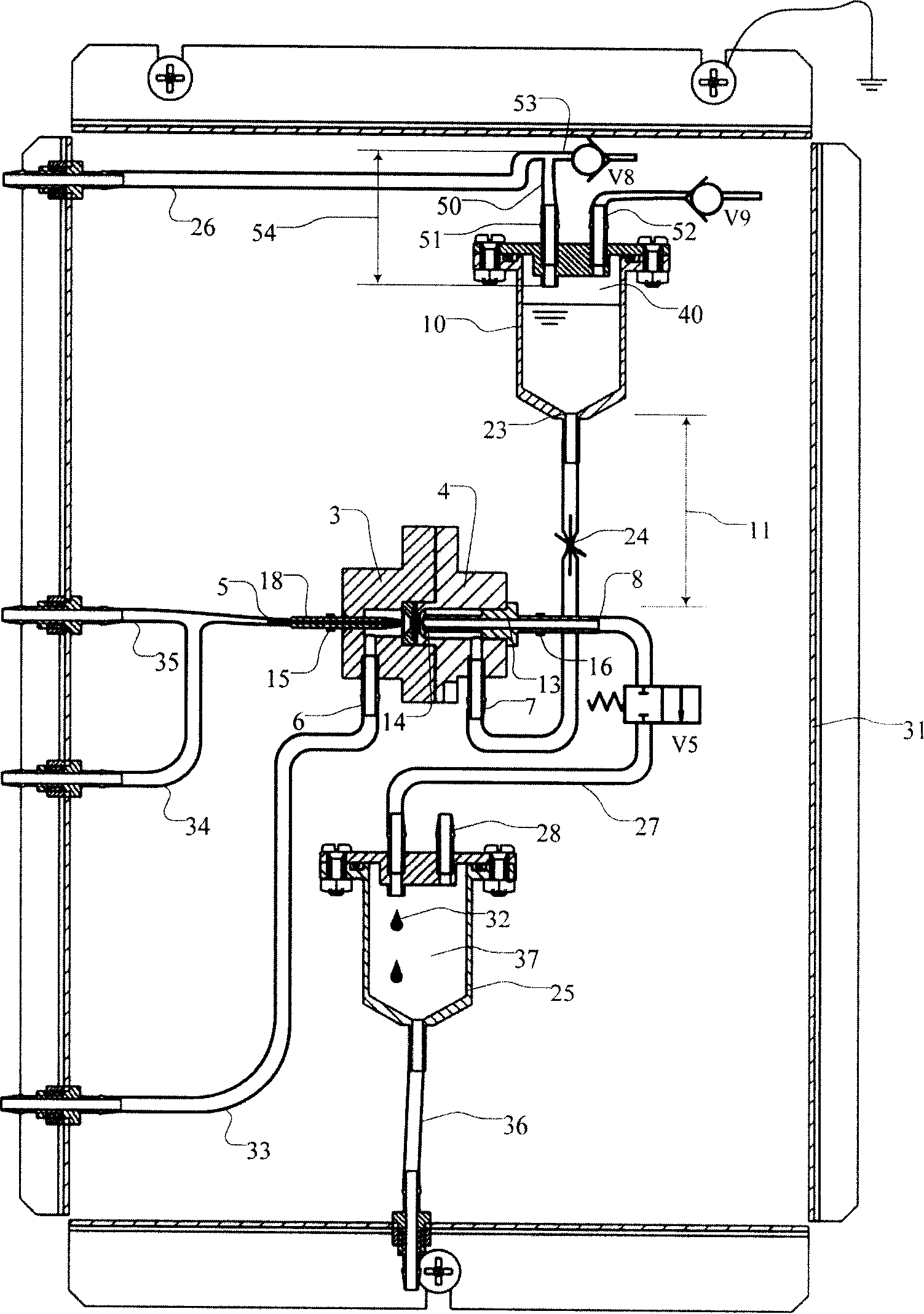
[0042] As shown in FIGS. 1 and 3 , a sheath flow impedance particle analyzer according to an exemplary embodiment of the present invention includes a counting cell 1 and a counting circuit 2 . The counting tank 1 includes a front tank 3 and a rear tank 4, the front tank 3 includes a particle suspension inlet 5 (served by the sample needle 18 at an end outside the counting tank) and a front sheath fluid inlet 6, the rear tank 4 Including a rear sheath liquid inlet 7 and a waste liquid outlet 8 (acted by the outlet pipe 13 at the end outside the counting cell); the front and rear sheath liquids are conductive and particle-free, which are respectively in the front and rear cells during use Form the front and rear sheath flows 9,12; the material of the sample needle 18 and the outlet pipe 13 is conductive metal; a rear sheath isolation pool 10 is located at a position higher than the counting pool 1 (especially the rear pool 4), and it is at the liquid level The back sheath flow 1...


PUM


Abstract

The invention puts forward a sheath flow impedance particle analyzer, comprising a counting cell, a counting circuit, a latter sheath partition cell and a liquid waste partition cell; wherein, the counting cell comprises a former cell and a latter cell; the former cell comprises a particle suspension liquid inlet and a former sheath liquid inlet; the latter cell comprises a latter sheath liquid inlet and a liquid waste outlet; a hole is arranged between the former cell and the latter cell which are connected with the counting circuit through electrode; the latter sheath liquid stored in the latter sheath partition cell can automatically and continuously flow into the latter cell under the gravitation and the internal negative pressure in the latter cell; the latter sheath partition cell can make the internal liquid passageway, which connects the inlet and the outlet of the latter sheath partition cell, insulated by the air; the liquid waste partition cell can make the internal liquid passageway insulated, which connects the inlet and the outlet of the liquid waste partition cell. The invention has the advantages of preventing the reflowing of the sample liquid in the process of detecting, reducing the signal noise effectively, increasing the detecting sensitivity of the particle and avoiding the electromagnet noise introduced to the counting cell from the latter sheath partition cell or the liquid waste partition cell.

Description

technical field [0001] The invention relates to a sheath flow impedance method particle analyzer, which can use the sheath flow impedance method to detect and analyze the number and volume of particles and other applications. Background technique [0002] The use of sheath flow impedance method for particle number and volume detection can be traced back to US patents US 3,793,587 and US 3,810,010 in 1974. Its common basic components are: front pool, back pool, small hole, sample needle, electrode, and detection circuit; the front and back pools are connected by a small hole, the sample needle is coaxial with the small hole, and its outlet is placed at a distance from the front pool. The position near the small hole can input the particle suspension (called sample flow) to the counting cell. The front and rear cells each have a source of conductive liquid without particles, which are called the front sheath flow and the back sheath flow. Sheath flow: The pressure of the fron...

Claims


Application Information

Patent Timeline
IPC IPC(8): G01N15/12G01N15/00G01N27/02
Inventor 罗成颜彦祝捷
Owner SHENZHEN MINDRAY BIO MEDICAL ELECTRONICS CO LTD
Learn More