Method of preparing a carbonaceous material for an emitter of an electron emission device

An electron emission device, carbide technology, applied in the direction of the cold cathode of the discharge tube, the main electrode of the discharge tube, etc., can solve the problems of large field enhancement factor β, short life, poor uniformity, etc.

Inactive Publication Date: 2008-05-21
SAMSUNG SDI CO LTD +1
View PDF1 Cites 11 Cited by
  • Summary
  • Abstract
  • Description
  • Claims
  • Application Information

AI Technical Summary

Problems solved by technology

[0011] However, the field enhancement factor β of ordinary fiber-type carbon nanotubes is large
Fiber-type carbon nanotube materials have many problems, such as poor uniformity, short lifetime, etc.
When producing fibrous carbon nanotubes using pastes, inks, slurries, etc., there are production problems compared to other materials in granular form
In addition, the raw materials are too expensive

Method used


Image

  • Method of preparing a carbonaceous material for an emitter of an electron emission device
  • Method of preparing a carbonaceous material for an emitter of an electron emission device
  • Method of preparing a carbonaceous material for an emitter of an electron emission device

Examples


Embodiment 1

[0065] First, 100 g of granular α-SiC with an average particle diameter of 0.7 μm was prepared as a carbon precursor in a high-temperature furnace composed of a graphite reaction chamber, a transformer, and the like. At a rate of 0.5L per minute, the Cl 2The gas was applied to a high temperature furnace maintained at 1000°C for 7 hours. Then, 30 g of carbide-derived carbon was prepared by extracting silicon from the carbon precursor using a thermochemical reaction.

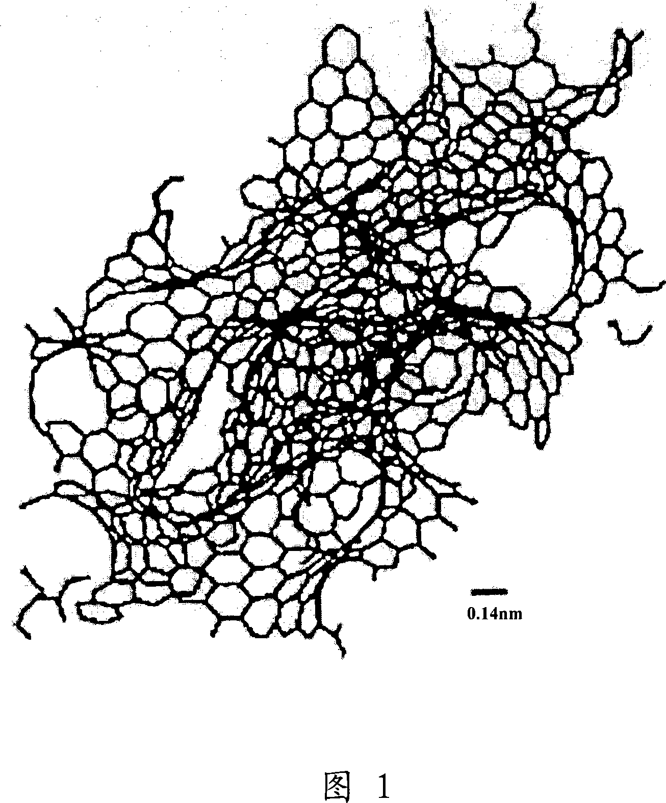
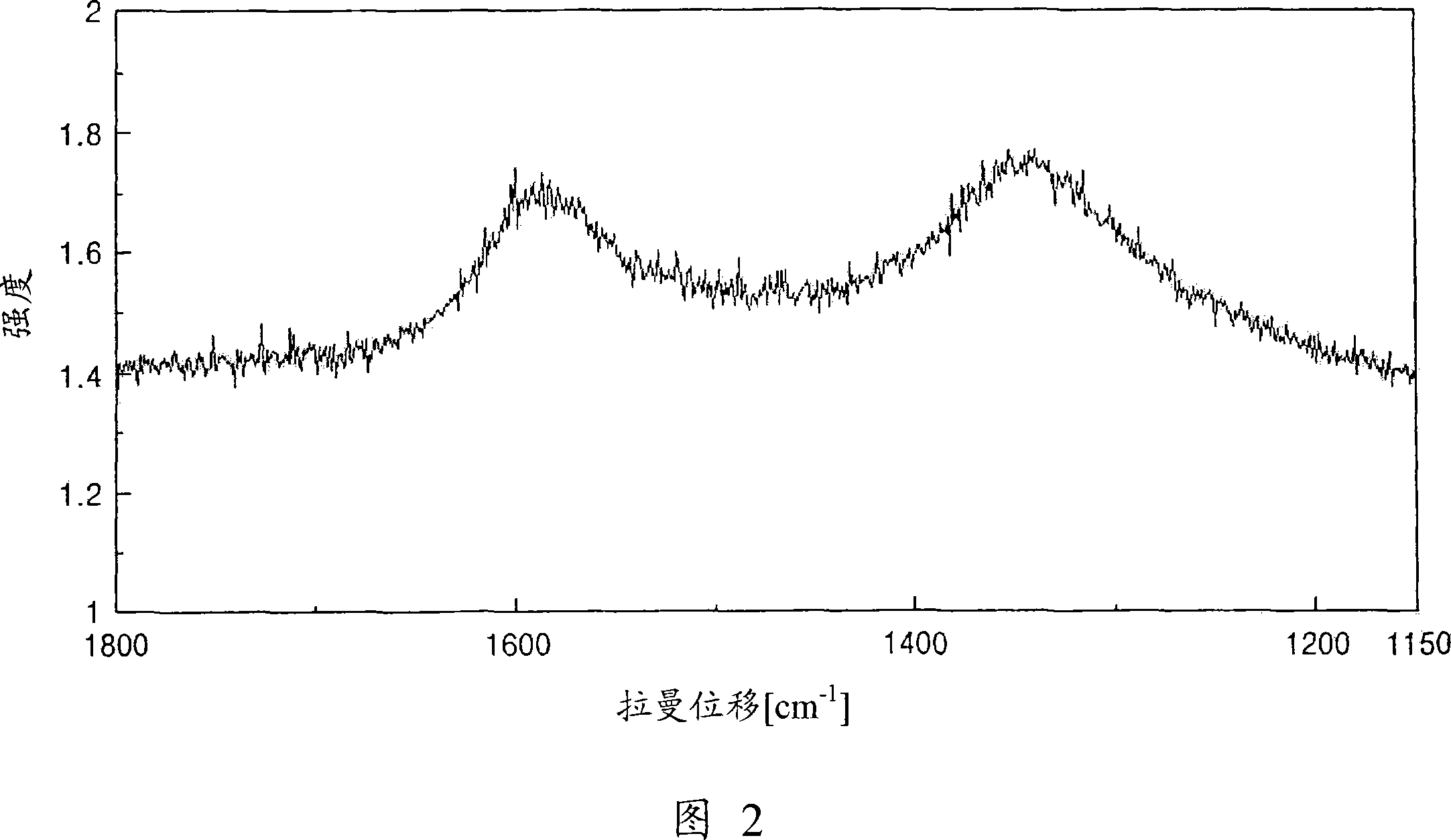
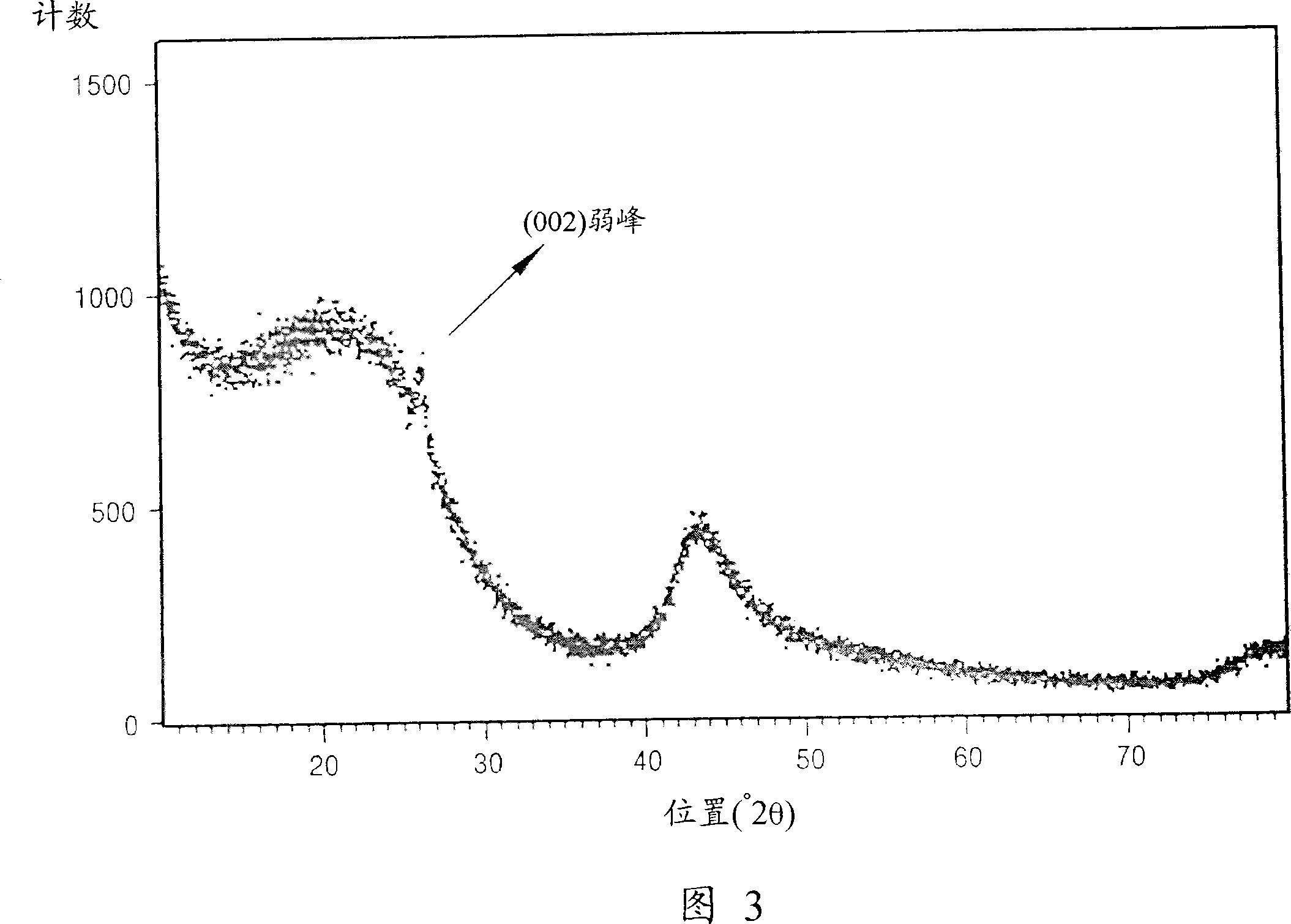
[0066] Carbon from carbides was analyzed using Raman peak analysis, X-ray diffraction and electron microscopy. I G / I D The ratio is 0.5 to 1. A weak peak of the graphite (002) plane can be observed at 2θ=25°. The electron diffraction pattern is a halo-pattern representing amorphous carbon. In addition, according to the method of Brunauer, Emmett and Teller (BET method), the specific surface area of ​​the carbide-derived carbon synthesized by this method is 1000 to 1100 m 2 / g.

Embodiment 2

[0068] 13 g of carbide-derived carbon were prepared in the same manner as in Example 1, except that 100 g of granular ZrC having an average particle diameter of 3 μm was used as a starting carbide compound, and heat-treated at 600° C. for 5 hours. Carbon derived from carbides was analyzed using Raman peak analysis. I G / I D The ratio is 1 to 1.3. Using the X-ray diffraction method, a weak single peak of the graphite (002) plane can be observed at 2θ=25°. In addition, according to the BET method, the specific surface area of ​​the carbide-derived carbon synthesized by this method is 1200m 2 / g.

Embodiment 3

[0070] 25 g of carbide-derived carbon were prepared in the same manner as in Example 1, except that 100 g of granular Al with an average particle size of 3 μm was used 4 C 3 , as the starting carbide compound, and heat-treated at 700°C for 5 hours. Carbon derived from carbides was analyzed using Raman peak analysis and X-ray diffraction. I G / I D The ratio is 1 to 3.2. A weak singlet of the graphite (002) plane was observed at 2Θ = 25°. Carbon from carbides was analyzed using high resolution TEM. Many graphite stripes can be observed, as shown in Figure 10 and Figure 11. In addition, according to the BET method, the specific surface area of ​​carbide-derived carbon synthesized by this method is 1050 to 1100 m 2 / g.


PUM

PropertyMeasurementUnit
specific surface areaaaaaaaaaaa
diameteraaaaaaaaaa
particle sizeaaaaaaaaaa

Abstract

Provided are carbide derived carbon materials prepared by thermochemically reacting carbide compounds and a halogen containing gas and extracting all atoms of the carbide compounds except carbon atoms, wherein the intensity ratios of the graphite G band at 1590 cm -1 to the disordered-induced D band at 1350 cm-1 are in the range of 0.3 through 5 when the carbide derived carbon is analyzed using Raman peak analysis, wherein the BET surface area of the carbide derived carbon is 1000 m 2 /g or more, wherein a weak peak or wide single peak of the graphite (002) surface is seen at 2 = 25 DEG when the carbide derived carbon is analyzed using X-ray diffractometry, and wherein the electron diffraction pattern of the carbide derived carbon is the halo pattern typical of amorphous carbon when the carbide derived carbon is analyzed using electron microscopy.

Description

[0001] Cross References to Related Applications [0002] This application claims the priority of Russian Patent Application No. 2006137605 filed in Rospatent Office on October 24, 2006 and Korean Patent Application No. 2006-126401 filed in Korean Intellectual Property Office on December 12, 2006, which The disclosure is incorporated herein by reference in its entirety. technical field [0003] Several aspects of the present invention relate to carbon derived from carbide (carbide derived carbon), emitters for cold cathodes comprising the carbon derived from carbides, and electron emission devices comprising the emitters; more particularly, the present invention relates to Carbon derived from carbides, emitters for cold cathodes comprising the carbon derived from carbides, and electron emission devices comprising the emitters, the carbide-extended carbons can be used more efficiently than methods used to produce conventional carbon nanotubes Inexpensive process preparation wh...

Claims


Application Information

Patent Timeline
Patent Type & Authority Applications(China)
IPC IPC(8): C01B31/02H01J1/30
Inventor 金润珍张东植金载明文希诚加布杜林·P·加里福维科戴维多夫·S·尼科莱维科科拉布利夫·V·瓦西利维科克拉夫奇克·A·埃菲莫维科索科洛夫·V·瓦西利维科库库什基纳·Y·亚历山德罗夫纳特雷什琴科·G·费多罗维科
Owner SAMSUNG SDI CO LTD
Why Eureka
Try Eureka