Low pressure difference voltage stabilizer

A low-dropout voltage regulator and voltage divider circuit technology, which is applied in the direction of instruments, electric variable adjustment, control/regulation systems, etc., can solve the problems of internal compensation not strong enough, not suitable for low current, large transconductance, etc., to reduce current Consumption level, strong stability, and the effect of improving output impedance

Inactive Publication Date: 2008-05-21
WUXI ZGMICRO ELECTRONICS CO LTD
View PDF0 Cites 30 Cited by
  • Summary
  • Abstract
  • Description
  • Claims
  • Application Information

AI Technical Summary

Problems solved by technology

However, this design also requires a larger transconductance, which requires a larger current, and is not suitable for low-current design requirements.
[0006] There are also some traditional LDOs because the internal compensation is not strong enough, the output capacitor must use a high ESR (Equivalent Series Resistance, equivalent series resistance) tantalum capacitor or a high-capacity ceramic capacitor to generate an external zero point to be stable, usually small and medium-capacity Tantalum capacitors are much more expensive than ceramic capacitors, and the larger the capacitance, the higher the price of the same type of capacitor

Method used


Image

  • Low pressure difference voltage stabilizer
  • Low pressure difference voltage stabilizer
  • Low pressure difference voltage stabilizer

Examples


no. 1 example

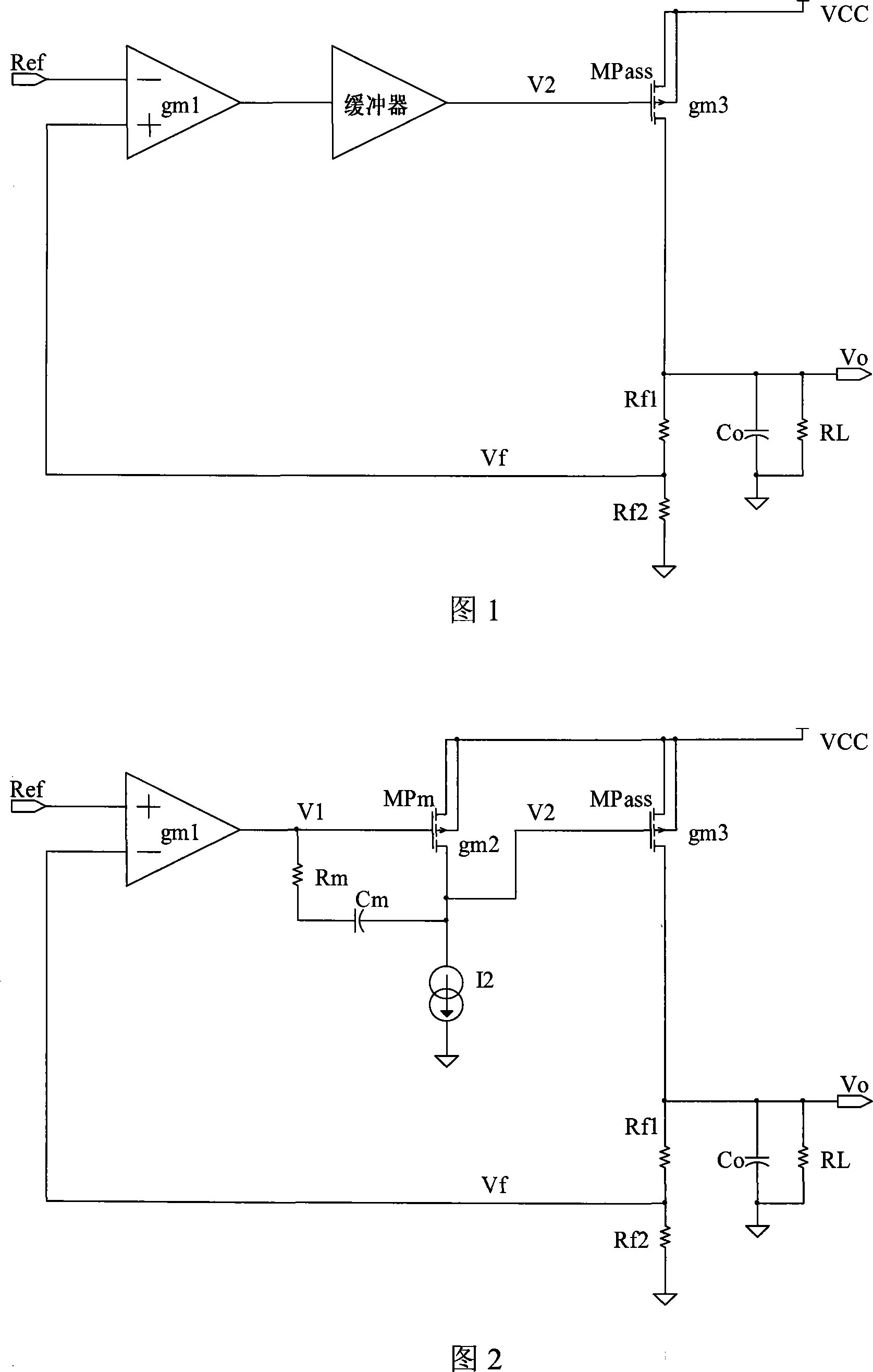
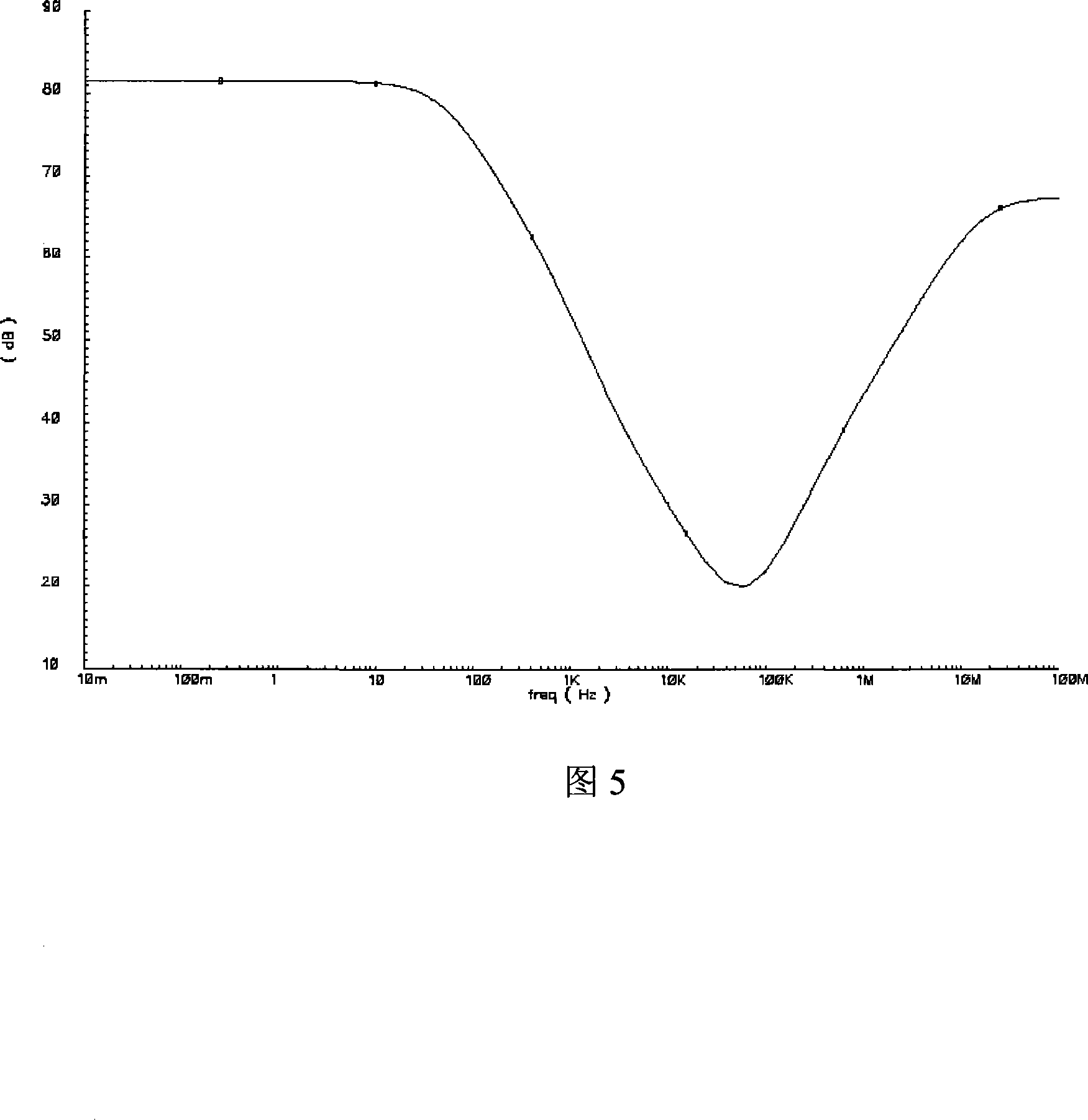
[0034] Like the prior art, the low dropout regulator of this embodiment also includes a differential amplifier circuit, an output amplifier circuit and a voltage divider circuit. The output amplifier circuit includes a PMOS transistor (also referred to as an output transistor) whose source is connected to the input power supply voltage Vdd, and an output capacitor Co connected between the voltage output point D (that is, the node from which the output voltage Vout is drawn) and ground, The resistor Resr in the figure is the equivalent series resistance of the output capacitor Co, R L Indicates the load. The two input terminals of the differential amplifier circuit are respectively connected to the reference voltage Ref and the voltage dividing point A of the voltage dividing circuit, and its output terminal N1 is connected to the gate of the PMOS transistor. The voltage dividing circuit is connected between the voltage output point and the ground. On this basis, in this embo...

no. 2 example

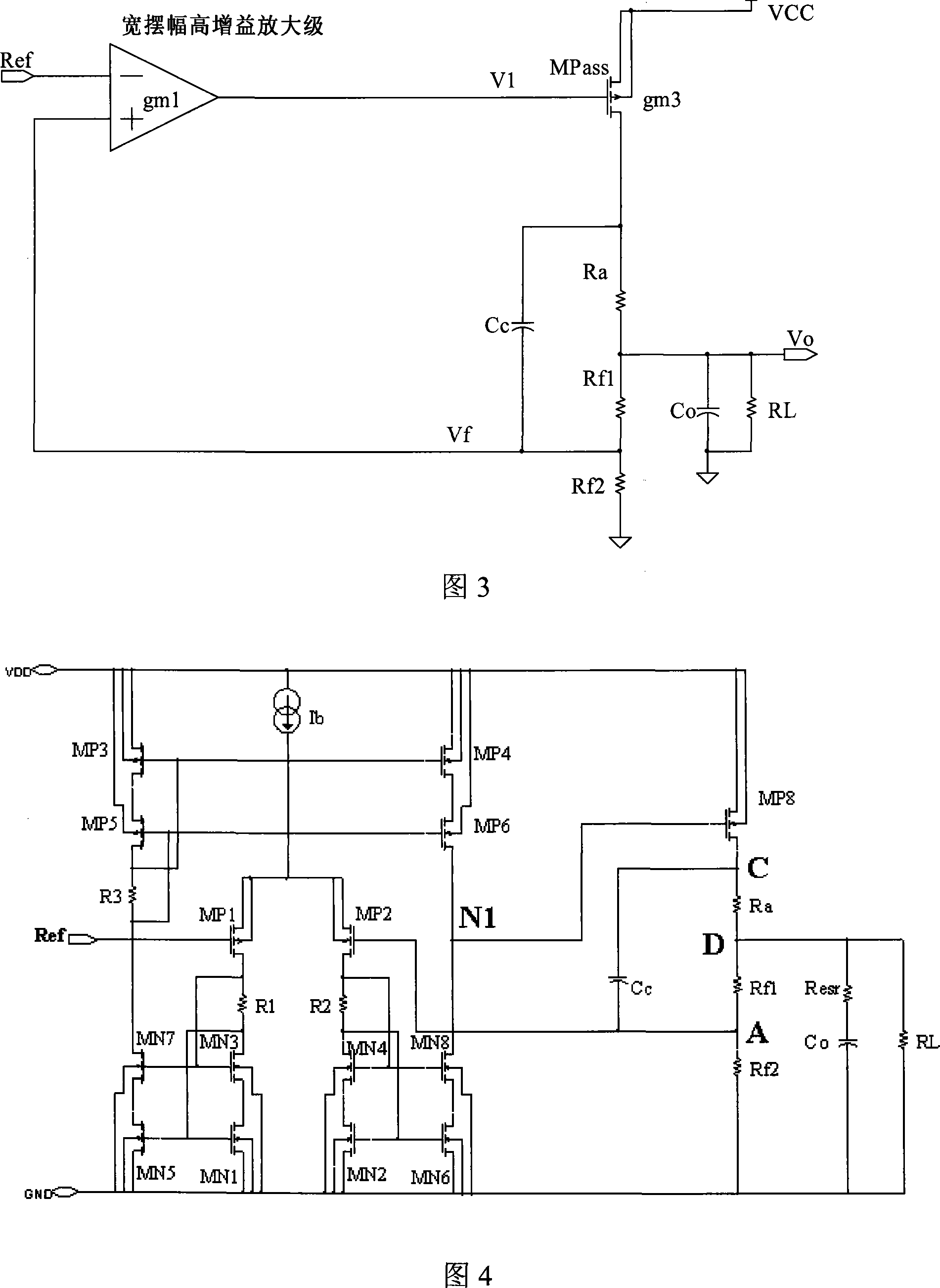
[0062] In the first embodiment, in order to realize the double zero pair compensation, the resistance R a The resistance value is very small, and metal resistors are generally used. The circuit structure adopted in this embodiment improves on this problem.

[0063] The structure of the low dropout voltage regulator of this embodiment is shown in FIG. 6 and FIG. 7 . The only difference from the circuit of the first embodiment is that a PMOS transistor MP7 is added to the output amplifier circuit. The source of MP7 is connected to the input voltage power supply Vdd, the drain is connected to the voltage output point D, and the gate is connected to the gate of MP8. In this implementation, the width-to-length ratio (W / L) of MP8 MP8 Far smaller than MP7's width-to-length ratio (W / L) MP7 , such as 1 / 10000 to 1 / 10. The current flowing through MP8 and Ra will be much smaller than the current flowing through MP7.

[0064] Suppose N=(W / L) MP7 / (W / L) MP8 , and then analyze the str...


PUM


Abstract

A kind of low-dropout regulator, comprising a differential amplifier circuit, an output amplifier circuit and a voltage divider circuit, said output amplifier circuit comprises a PMOS transistor MPass1 whose source is connected to the input supply voltage Vdd, and connected between the voltage output point and The output capacitor Co between the ground, the two input terminals of the differential amplifier circuit are respectively connected to the reference voltage Ref and the voltage division point of the voltage divider circuit, the output terminal of the differential amplifier circuit is connected to the gate of the PMOS transistor, and the The voltage divider circuit is connected between the voltage output point and the ground, and is characterized in that it also includes a resistor Ra connected between the drain of the PMOS transistor MPass1 and the voltage output point, and a resistor Ra connected between the drain of the PMOS transistor MPass1 and the capacitor Cc between the voltage divider points. The low dropout voltage regulator provided by the invention has the advantages of low quiescent current, high power supply suppression, strong stability, low dropout voltage and low cost, and meets the needs of practical applications.

Description

technical field [0001] The invention relates to a low-drop voltage stabilizer, in particular to a low-drop voltage stabilizer with ultra-low quiescent current. Background technique [0002] In electronic design applications, an ultra-low quiescent current low dropout regulator (Low Dropout Regulator, abbreviated as LDO, also known as a low dropout voltage regulator) is required in some cases, such as the power supply of a real-time clock circuit. In many portable electronic products, there is a real-time clock circuit, and this circuit needs to always work to ensure that the time is always measured. Even when some electronic devices are replacing batteries, the real-time clock circuit can still time accurately. After down, there is only one capacitor to maintain a small amount of power, so that the real-time clock circuit needs to work with a small current, and the low-dropout voltage regulator that provides power for the real-time clock circuit also needs to consume extreme...

Claims


Application Information

Patent Timeline
Patent Type & Authority Applications(China)
IPC IPC(8): G05F1/56
CPCG05F1/575
Inventor 王钊田文博尹航
Owner WUXI ZGMICRO ELECTRONICS CO LTD
Why Eureka
Try Eureka