Unlock instant, AI-driven research and patent intelligence for your innovation.

Radio frequency loopback test method and system and loopback test local oscillator providing method and apparatus

A loopback test and radio frequency technology, applied in the field of mobile communication, can solve the problem of high cost, achieve the effect of reducing material cost, overcoming high material cost, and eliminating the hidden danger of stray interference

Active Publication Date: 2008-05-21
HUAWEI TECH CO LTD
View PDF0 Cites 3 Cited by
  • Summary
  • Abstract
  • Description
  • Claims
  • Application Information

AI Technical Summary

Problems solved by technology

[0009] Embodiments of the present invention provide a radio frequency loopback test method and device, and a loopback test local oscillator providing method and device, so as to solve the problem of providing a duplex interval frequency for an independent loopback test local oscillator circuit in the radio frequency loopback test process in the prior art signal and lead to costly defects

Method used


Image

  • Radio frequency loopback test method and system and loopback test local oscillator providing method and apparatus
  • Radio frequency loopback test method and system and loopback test local oscillator providing method and apparatus
  • Radio frequency loopback test method and system and loopback test local oscillator providing method and apparatus

Examples


no. 1 example

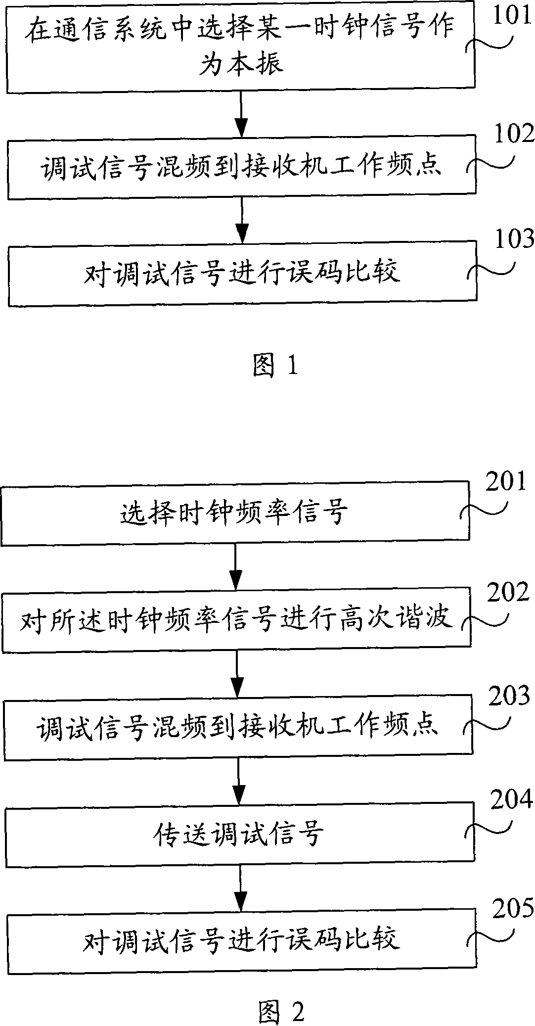
[0032] As shown in Figure 1, it is the flowchart of the first embodiment of the radio frequency loopback test method of the present invention, and the radio frequency loopback test method is specifically as follows:

[0033] Step 101, selecting a certain clock signal as a local oscillator in the communication system, and the frequency of the local oscillator is the same as that of the duplex interval of the communication system;

[0034] Step 102, mix the debugging signal to the receiver operating frequency according to the local oscillator, and send the debugging signal with the carrier signal of the transmitter;

[0035] Step 103 , receiving the debugging signal, and performing bit error comparison on the debugging signal.

[0036] In the radio frequency loopback test method of the embodiment of the present invention, in the communication system, the clock signal with the same duplex interval frequency as the communication system is selected as the local oscillator, and the ...

no. 2 example

[0039] As shown in Figure 2, it is a flowchart of the second embodiment of the radio frequency loopback test method of the present invention. The second embodiment of the radio frequency loopback test method of the present invention is based on the first embodiment of the radio frequency loopback test method of the present invention. The details of the RF loopback test method are as follows:

[0040] Step 201, select a certain clock signal in the communication system;

[0041] Step 202, performing high-order harmonics on the clock signal to generate a high-order harmonic signal, and the high-order harmonic signal is the same as the duplex interval frequency of the communication system;

[0042] Step 203, using the high-order harmonic signal as a local oscillator, and mixing the debugging signal to the working frequency of the receiver;

[0043] Step 204, using the carrier signal of the transmitter to send the debugging signal;

[0044] Step 205, receiving the debugging signa...

no. 3 example

[0047] As shown in Figure 3, it is a flowchart of the third embodiment of the radio frequency loopback test method of the present invention. The third embodiment of the radio frequency loopback test method of the present invention is based on the first embodiment of the radio frequency loopback test method of the present invention. The details of the RF loopback test method are as follows:

[0048] Step 301, select a certain clock signal from the clock signals within the adjustable range of the operating frequency point of the transmitter or receiver with the frequency difference between the duplex interval frequency of the communication system;

[0049] Step 302, adjusting the operating frequency of the transmitter or receiver so that the duplex interval frequency of the communication system is equal to the frequency of the clock signal;

[0050] Step 303, using the clock signal as a local oscillator, and mixing the debugging signal to the working frequency of the receiver; ...


PUM


Abstract

The invention relates to a radio frequency loop-back test method, which comprises following steps: a certain clock signal is selected as local oscillator in communication system, the local oscillator and the communication system duplexer have same interval frequencies, the debugging signal is mixed to the working frequency point of receiver according to the local oscillator and transferred, the error code comparison is performed on the debugging signal. The invention relates to a radio frequency loop-back test system, which comprises a transmitting end and a receiving end, wherein, the transmitting end is used to select clock signal as the local oscillator, the local oscillator and the communication system duplexer have same interval frequencies, the debugging signal is mixed to the working frequency point of receiver according to the local oscillator and transferred; the receiving end is used for error code comparison. The invention also relates to a loop-back test local oscillator providing method and device, which comprises a first selection module and a local oscillator generation module, wherein, the first selection module is used for selecting a certain clock signal in communication system and the local oscillator generation module used for enabling the clock signal be generated into the local oscillator. The invention has an advantage of effectively overcoming the detects of high cost material, high manufacturing cost, high malfunction ratio and disperse interfered hidden danger in the prior art.

Description

technical field [0001] Embodiments of the present invention belong to the field of mobile communications, and in particular, to a method and system for radio frequency loopback testing and a method and device for providing a local oscillator for loopback testing. Background technique [0002] In order to facilitate the maintenance of the network, the transmitter and receiver of the communication system automatically detect and locate faults through the radio frequency loopback test method in the air interface (no service) state. At this time, a special loopback is added to the transmitter and receiver circuits. Test the local oscillator circuit, and mix the transmitted signal modulated into a fixed code pattern to the uplink frequency point corresponding to the receiving frequency band, and compare the bit errors after demodulation and decoding in the receiver, so as to judge the difference between the transmitter and the receiver. whether the channel is faulty. RF loopback...

Claims


Application Information

Patent Timeline
IPC IPC(8): H04Q7/34H04B17/00H04L1/00
CPCH04L1/0045H03J7/02H04W24/06H04W28/04
Inventor 薛裕胜
Owner HUAWEI TECH CO LTD
Features
  • R&D
  • Intellectual Property
  • Life Sciences
  • Materials
  • Tech Scout
  • Unparalleled Data Quality
  • Higher Quality Content
  • 60% Fewer Hallucinations
Learn More