Suspension board with circuit and producing method thereof
A suspension substrate and circuit technology, which is applied in the manufacture of metal core circuits, reinforcement of conductive patterns, and secondary processing of printed circuits. Effects of simple manufacturing, reduced manufacturing man-hours, and simplified structure
- Summary
- Abstract
- Description
- Claims
- Application Information
AI Technical Summary
Problems solved by technology
Method used
Image

Examples
Embodiment 1
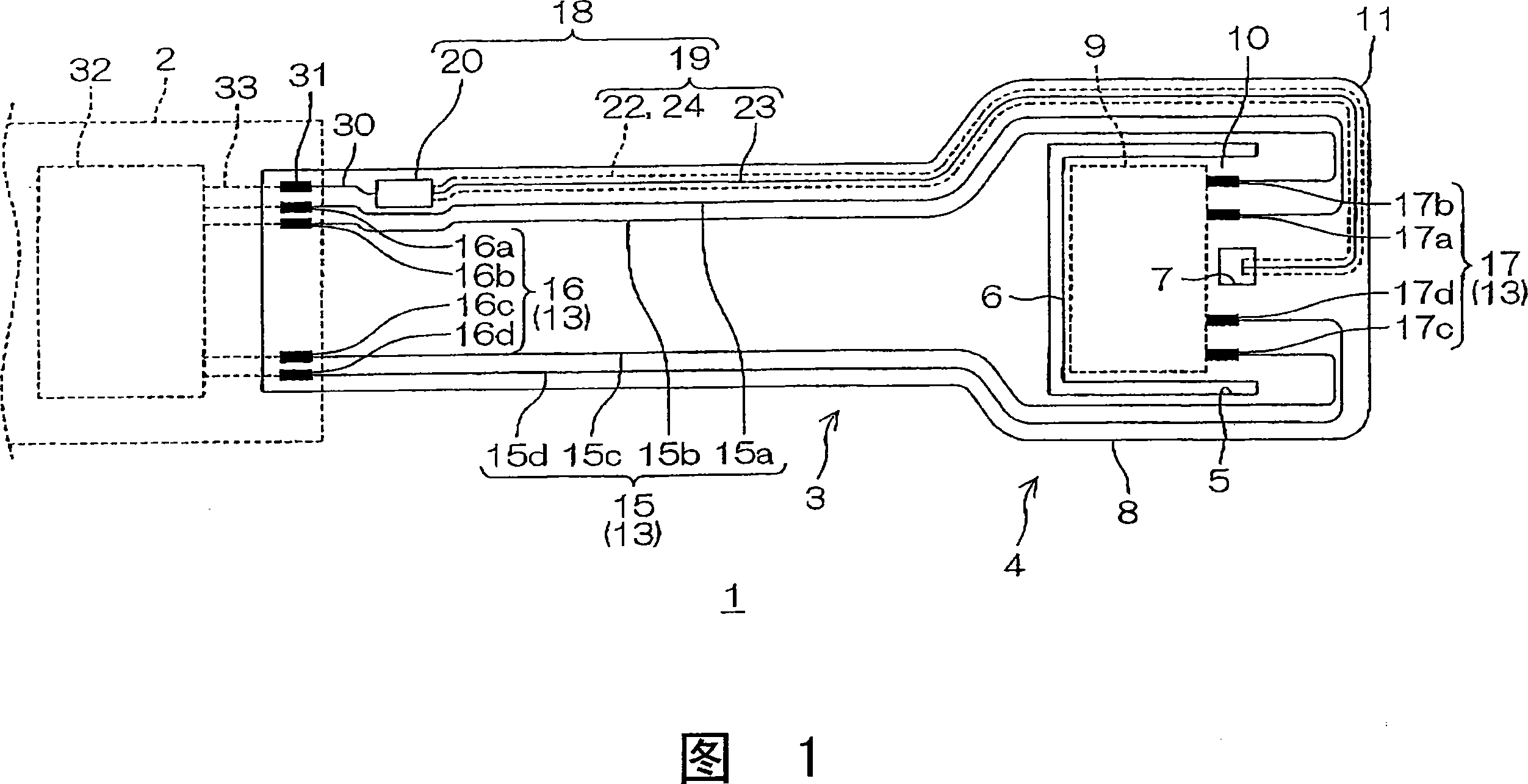
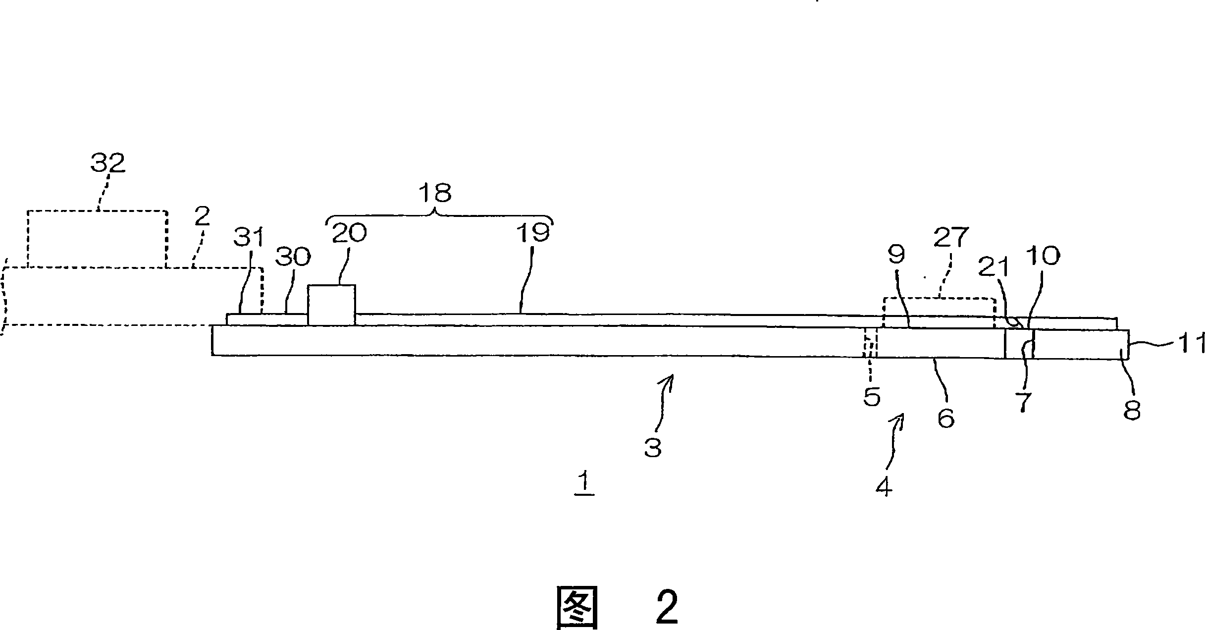
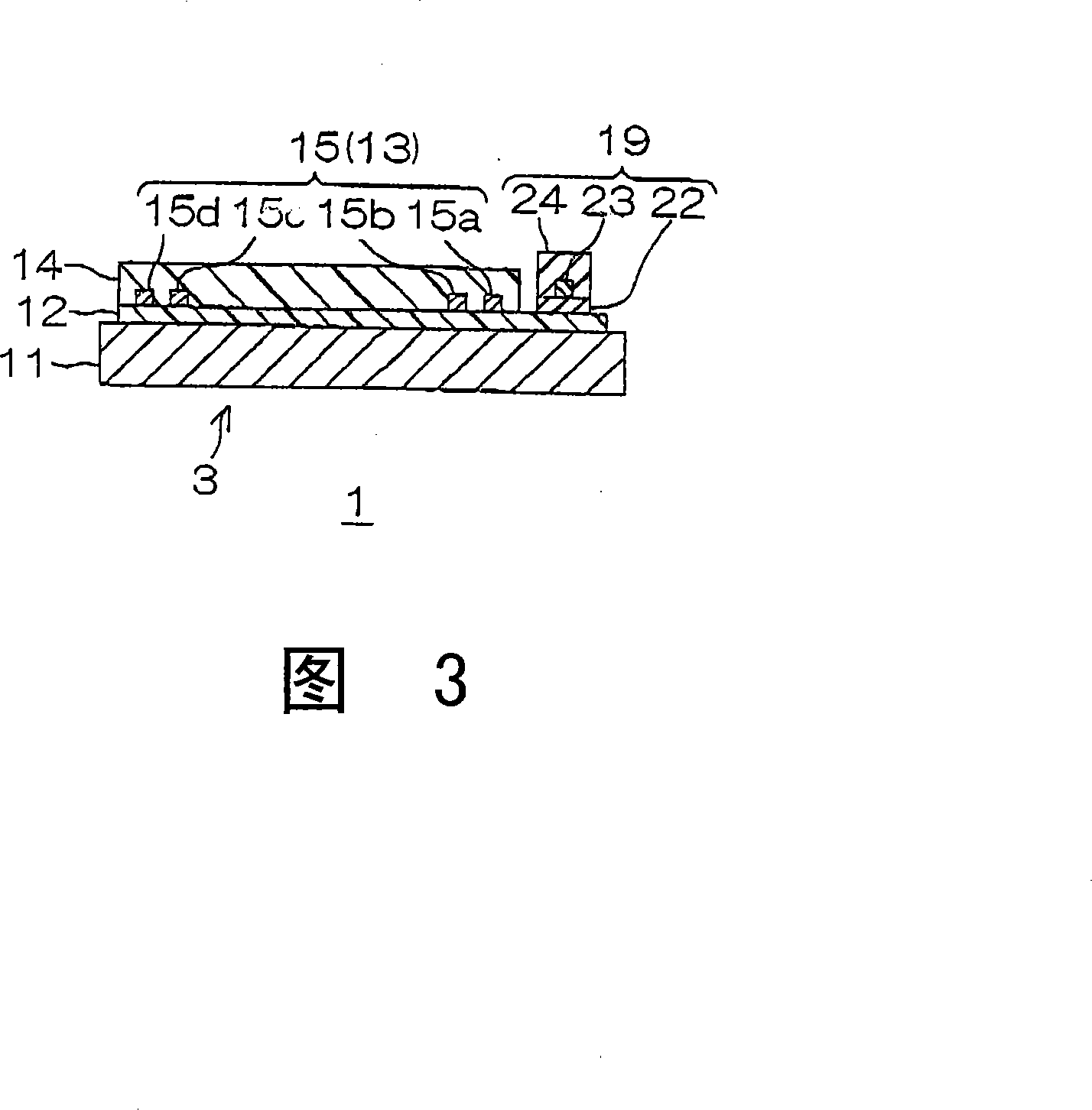
[0158] Embodiment 1 (A form in which a light guiding path is provided on a substrate insulating layer)
[0159] A metal support substrate made of stainless steel with a thickness of 20 μm was prepared (see FIG. 4( a )).
[0160] Next, an insulating base layer made of polyimide resin was formed on the metal supporting board using the above-mentioned pattern. The thickness of the substrate insulating layer was 10 µm.
[0161] Next, by an additive method, a conductor pattern made of copper, a supply wiring, and a supply terminal portion were simultaneously formed. The thickness of these is 10 μm.
[0162] Next, a cover insulating layer made of polyimide resin was formed on the base insulating layer using the above-mentioned pattern. The thickness of the insulating cover layer is 5 μm. In this manner, the base insulating layer, the conductor pattern, and the cover insulating layer are sequentially laminated on the metal supporting substrate (see FIG. 4( b )).
[0163] Next, a...
Embodiment 2
[0176] Embodiment 2 (a form in which a light guide path is provided on a cover insulating layer)
[0177] In Example 2, a light guide path is provided on the insulating cover layer, and a light-emitting element is provided on the insulating cover layer. In the same manner as in Example 1, a suspension board with a circuit is manufactured (refer to FIGS. 7).
[0178] That is, the cover insulating layer is formed such that its outer peripheral edge is substantially at the same position as the outer peripheral edge of the base insulating layer in plan view (see FIG. 7( b )).
[0179] In addition, the light guide path is formed so that it overlaps with the first wiring on the cover insulating layer in the wiring part and the external connection part of the universal joint part, and in the terminal forming part, faces the first wiring part on the cover insulating layer. Offset on the other side in the width direction. In addition, a light emitting element is provided on the insul...
Embodiment 3
[0180] Embodiment 3 (a form in which the substrate insulating layer also serves as the lower cladding layer, and the cover insulating layer also serves as the upper cladding layer)
[0181] A metal support substrate made of stainless steel with a thickness of 20 μm was prepared (see FIG. 8( a )).
[0182] Next, an insulating base layer made of polyimide resin was formed on the metal supporting board in the above-mentioned pattern. The refractive index of the substrate insulating layer at a wavelength of 830 nm was 1.541. In addition, the thickness of the insulating substrate layer was 6 μm (see FIG. 8( b )).
[0183] Next, by an additive method, a conductor pattern made of copper, a supply wiring, and a supply terminal portion were simultaneously formed on the insulating substrate layer (see FIG. 8(c)). The thickness of these is 10 μm.
[0184] Next, a core layer is formed on the substrate insulating layer.
[0185] In order to form the core layer with the above pattern, f...
PUM
| Property | Measurement | Unit |
|---|---|---|
| Thickness | aaaaa | aaaaa |
| Thickness | aaaaa | aaaaa |
| Epoxy equivalent | aaaaa | aaaaa |
Abstract
Description
Claims
Application Information
 - R&D
- Intellectual Property
- Life Sciences
- Materials
- Tech Scout
- Unparalleled Data Quality
- Higher Quality Content
- 60% Fewer Hallucinations
Browse by: Latest US Patents, China's latest patents, Technical Efficacy Thesaurus, Application Domain, Technology Topic, Popular Technical Reports.
© 2025 PatSnap. All rights reserved.Legal|Privacy policy|Modern Slavery Act Transparency Statement|Sitemap|About US| Contact US: help@patsnap.com