Full-open permanent magnetism magnetic body for magnetic resonance image-forming
A magnetic resonance imaging, open technology, applied in applications, permanent magnets, measurement of magnetic variables, etc., can solve problems affecting the stability and uniformity of the magnetic field working area, adverse effects of magnetic field uniformity, and easy vibration of magnetic poles. Achieve the effect of improving the uniformity and stability of the magnetic field, improving the shimming efficiency, and reducing the total weight
- Summary
- Abstract
- Description
- Claims
- Application Information
AI Technical Summary
Problems solved by technology
Method used
Image
Examples
Embodiment 1
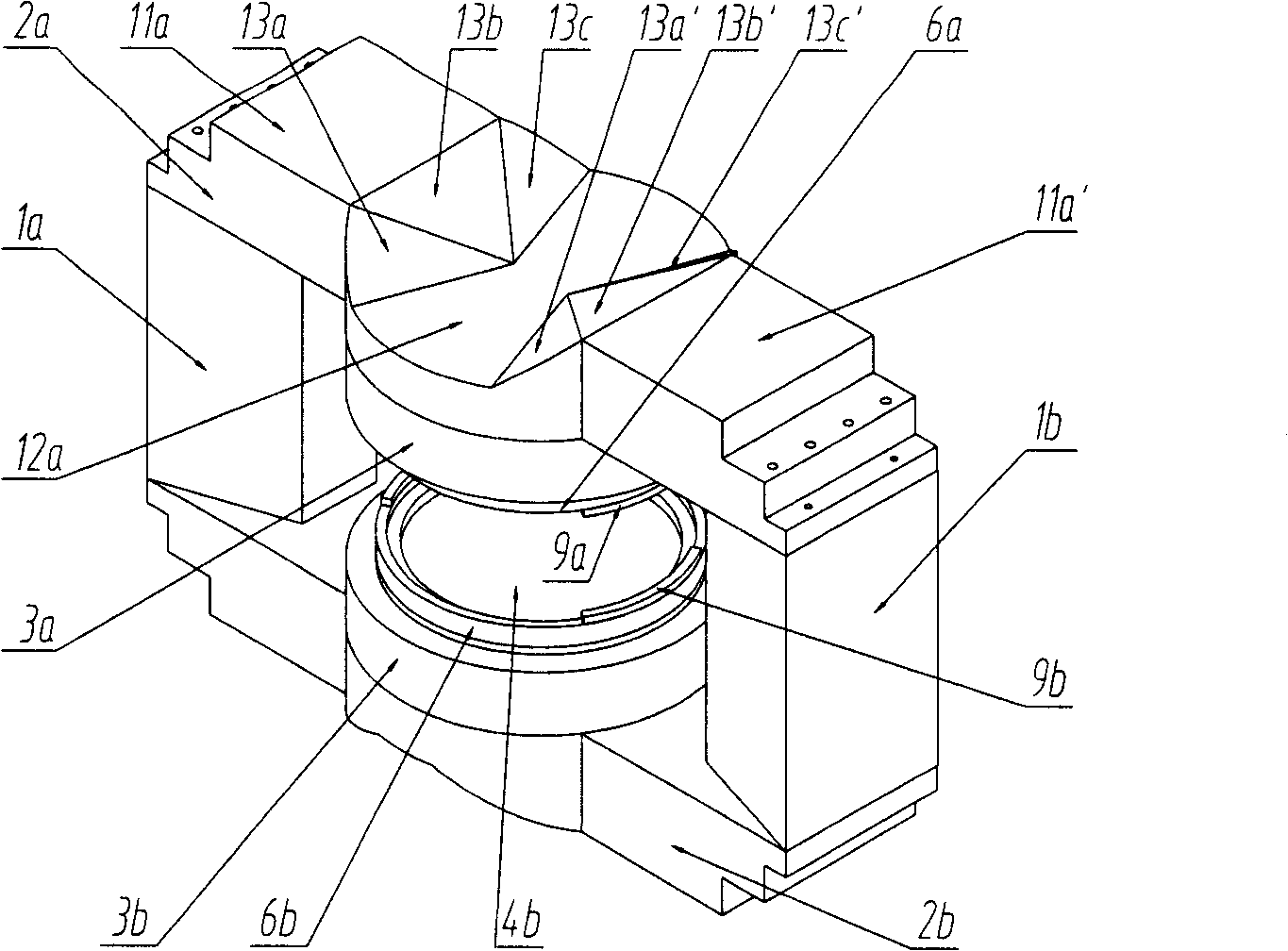
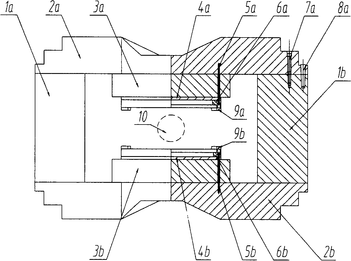
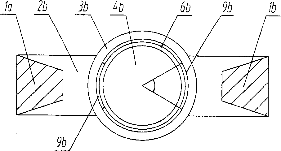
[0059] In this embodiment, the static magnetic field strength of the magnetic resonance imaging working area is 4000 Gauss, the main magnetic pole material is NdFeB rare earth permanent magnet, and the rest of the magnet is made of electrical pure iron. The main dimensions of the magnet main structure are: total height 1900mm, length 2800mm, width 650mm, the shortest distance between the two vertical yokes 1a and 1b is 1900mm, the shortest distance between the two horizontal yokes 2a and 2b is 1100mm, the upper and lower pole rings The distance between them is 450mm, the diameter of 10 balls in the working area is 400mm, the uniformity of the magnetic field is less than 20ppm, and the total weight of the magnet is less than 16 tons.
[0060] Such as figure 1 as shown, figure 1 It is an appearance view of a fully open permanent magnet for magnetic resonance imaging according to the first embodiment of the present invention. The upper and lower horizontal yokes 2a, 2b are para...
Embodiment 2
[0072] In this example, refer to Figure 7 with Figure 8 Be explained. in, Figure 7 It is an appearance diagram of a fully open permanent magnet for magnetic resonance imaging according to the second embodiment of the present invention, Figure 8 It is a front view of a fully open permanent magnet for magnetic resonance imaging according to the second embodiment of the present invention. The specific magnet structure is similar to that of Embodiment 1, and only the upper part will be described here.
[0073] Part of the material is removed from the side of the middle part of the transverse yoke 2a away from the main magnetic pole 3a, and the transverse yoke after material removal still maintains a left-right and front-back symmetry. Viewed from the front, after part of the material is removed, the upper surface of the middle part of the transverse yoke 2a (that is, the surface away from the main magnetic pole side) forms a trapezoidal depression, the inner bottom edge is...
PUM
 Abstract
Description
Claims
Application Information
 - R&D
- Intellectual Property
- Life Sciences
- Materials
- Tech Scout
- Unparalleled Data Quality
- Higher Quality Content
- 60% Fewer Hallucinations
Browse by: Latest US Patents, China's latest patents, Technical Efficacy Thesaurus, Application Domain, Technology Topic, Popular Technical Reports.
© 2025 PatSnap. All rights reserved.Legal|Privacy policy|Modern Slavery Act Transparency Statement|Sitemap|About US| Contact US: help@patsnap.com


