Unlock instant, AI-driven research and patent intelligence for your innovation.

Automatic focusing method

A technology of automatic focusing and driving unit, applied in the field of focusing, it can solve the problems of slow focusing speed, long total distance and long stroke, and achieve the effect of improving focusing speed, reducing backlash error and shortening stroke.

Inactive Publication Date: 2008-06-04
ASIA OPTICAL CO INC
View PDF0 Cites 16 Cited by
  • Summary
  • Abstract
  • Description
  • Claims
  • Application Information

AI Technical Summary

Problems solved by technology

[0010] However, although the above method can achieve the function of autofocus, it still has unsatisfactory effects, such as:
[0011] 1. From figure 2 It can be seen from the flow chart of FIG. 3 and the graph in FIG. 3 that the movement of the focusing lens group 101 operates in the manner of "turning back and running", and its moving positions are A, B, C, D, and E in sequence. When reaching a turning position (such as B, C, D) and needing to run back, the drive unit 13 must first be suspended before reverse rotation, which takes a long time, and the mechanical wear is also large, resulting in lower life expectancy and higher failure rate. high
[0012] 2. From the moving sequence in Figure 3, it can be seen that the way of running back and forth will repeatedly go back and forth between positions E and D, and the total moving distance is longer, resulting in a longer focusing time
[0013] 3. Every time you want to take a photo to focus, you will always return to the close-up position B to return to zero. At this time, if the last photo is a long-range shot, the activation position A will inevitably be close to the long-shot position F, and the next photo It is also necessary to shoot from a distance, and the focusing lens group 101 cannot perform a close-range zeroing action at the telephoto position F, but must first return to the close-up position B. In this way, it will cause a long travel time, a long time-consuming, and a slow focusing speed.

Method used


Image

  • Automatic focusing method
  • Automatic focusing method
  • Automatic focusing method

Examples


Embodiment Construction

[0049] The foregoing and other technical contents, features and effects of the present invention will be clearly presented in the following detailed description of preferred embodiments with accompanying drawings.

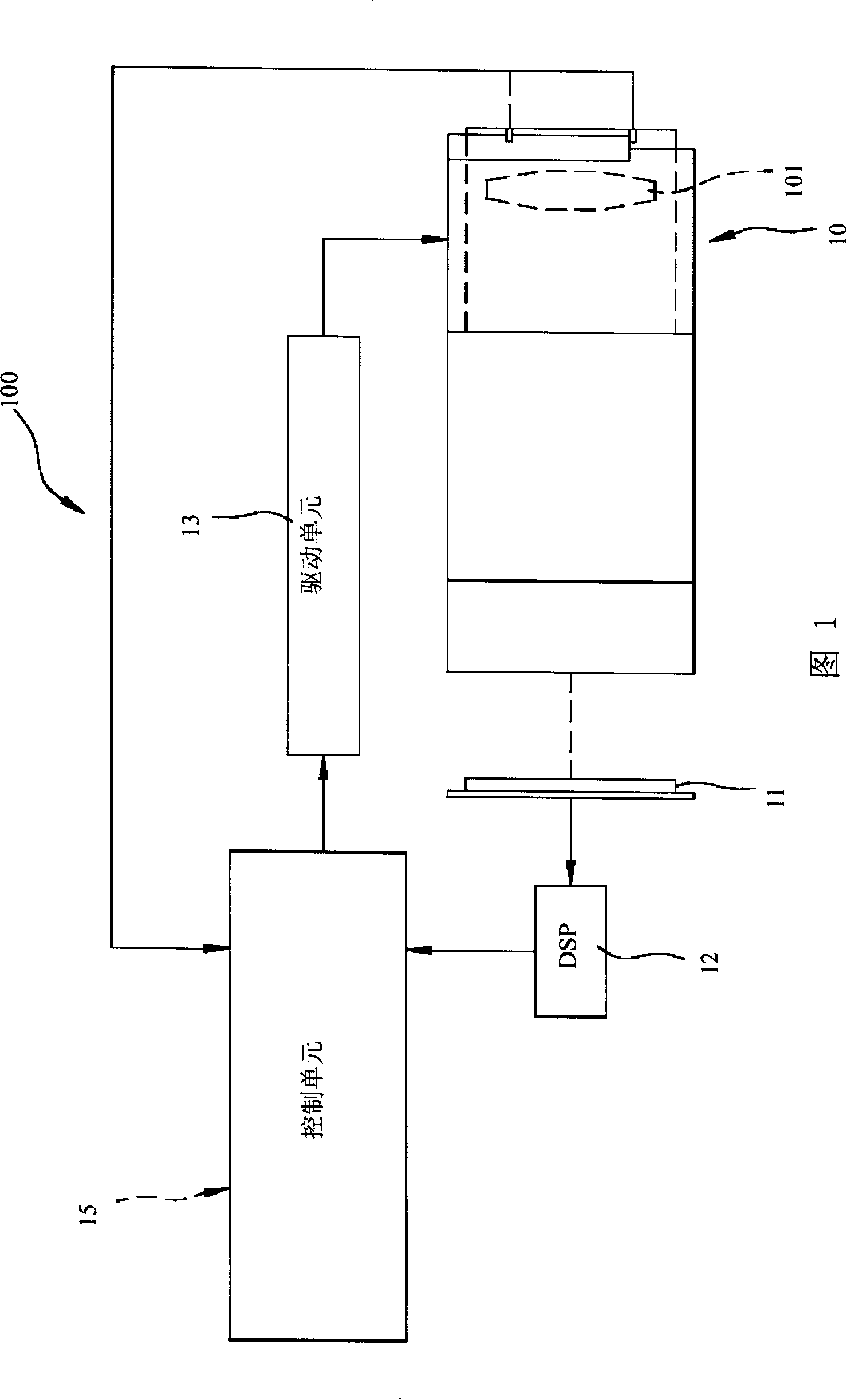
[0050] As shown in Figures 4, 5, and 6, the autofocus method of the present invention is suitable for use in an imaging device 200 to adjust the relative position of an optical system and a photosensitive component 22 to obtain an image in which an imaging surface falls within the depth of field range. The device 200 includes the above-mentioned optical system, a photosensitive component 22 for imaging, a signal processor 23 for receiving signals from the photosensitive component 22, a drive unit 24 for driving the focusing lens group 211 and the photosensitive component 22 to move relatively, and an electrical connection signal processing The controller 23 and the control unit 26 of the drive unit 24. Wherein, the optical system is composed of a lens 21 with a foc...


PUM


Abstract

The present invention relates to an automatic focusing method which is suitable to adjust the relative position of an optical system and a photosensitive component for leading an imaging plane to fall in a field depth range. The optical system comprises a focusing lens group. The automatic focusing method provided by the present invention firstly allows the focusing lens group and the photosensitive component to return to zero, then changes the relative position of the focusing lens group and the photosensitive component for predict an evaluation value that the imaging plane falls in the field depth range, and finally approaches toward the evaluation value until the imaging plane on the photosensitive component falls in the field depth range, thus automatic focusing is completed. During automatic focusing, as only one time of reentrant movement is needed, the speed can be greatly quickened, and the present invention can achieve the using effect of rapid focusing, little mechanical wear, long life span and low failure rate.

Description

technical field [0001] The invention relates to a focusing method, in particular to an automatic focusing method. Background technique [0002] As shown in Figures 1, 2, and 3, the autofocus function often appears in, for example, the camera system 100 of a digital camera, so that the user can quickly obtain the imaging state that the imaging plane falls within the depth of field range. 100 mainly includes a lens 10 with a focusing lens group 101, a photosensitive component 11, a signal processor 12 (DSP), a drive unit 13 that drives the focusing lens group 101 to move relative to the photosensitive component 11, and an electrical connection signal processing The controller 12 and the control unit 15 of the drive unit 13. [0003] The camera system 100 obtains an image result in which the imaging plane falls within the depth of field through an autofocus method, and the method includes the following steps: [0004] (A) When the digital camera is activated, regardless of th...

Claims


Application Information

Patent Timeline
IPC IPC(8): G03B13/36H04N5/225
Inventor 吴东颖
Owner ASIA OPTICAL CO INC
Features
  • R&D
  • Intellectual Property
  • Life Sciences
  • Materials
  • Tech Scout
  • Unparalleled Data Quality
  • Higher Quality Content
  • 60% Fewer Hallucinations
Learn More