

A time division duplex digital filter
A digital filter and digital filtering technology, applied in the direction of digital transmission system, duplex signal operation, digital technology network, etc., can solve the problems of power consumption, repeated waste of digital devices, waste of system power consumption, etc., to reduce costs and functions consumption, time division multiplexing, and cost reduction
- Summary
- Abstract
- Description
- Claims
- Application Information
AI Technical Summary
Problems solved by technology
Method used
Image

Examples
Embodiment 1
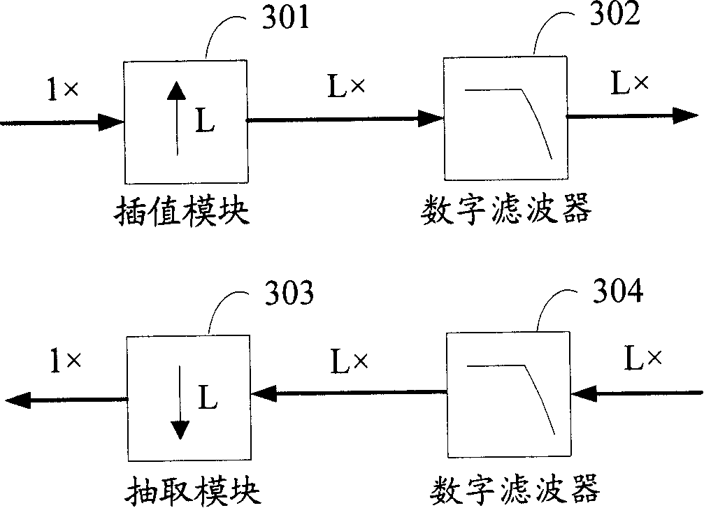
[0063] The first typical application is that the uplink and downlink baseband code rates are the same, only one level of interpolation / decimation is used in digital intermediate frequency processing, and the interpolation rate is the same as the decimation rate.
[0064] Usually, the design of the digital intermediate frequency processing module is very flexible, and it is easy to ensure the same interpolation / decimation rate at the stage of system design. The same as the decimation rate is called symmetric. image 3 It is a structural schematic diagram of an existing one-stage symmetrical interpolation / decimation filter. see image 3 Since the downlink baseband code rate and the uplink baseband code rate are 1 times (1×), the interpolation rate of the downlink interpolation module 301 and the extraction rate of the uplink decimation module 303 are all L times, therefore, the downlink digital filter 302 and the uplink digital filter Filter 304 works under the same code rate,...
Embodiment 2
[0080] The second typical application is that the uplink and downlink baseband code rates are the same, the digital intermediate frequency processing system uses multi-level interpolation / decimation, and the interpolation rate and decimation rate of the same level of interpolation / decimation are the same.
[0081] In practical applications, due to the high code rate of digital intermediate frequency processing, the filter order required to directly filter the received data is relatively large. Therefore, multi-stage interpolation / decimation filtering is usually used to implement interpolation / decimation filtering. The following takes two-level cascading as an example for illustration.
[0082] Figure 5 It is a schematic structural diagram of an existing two-stage symmetrical interpolation / decimation filtering cascade. see Figure 5 , the uplink baseband code rate and the downlink baseband code rate are 1 times (1×), in the two-stage cascaded interpolation / extraction, the in...
Embodiment 3
[0101] The third typical application is that the uplink and downlink baseband code rates are different, and the interpolation rate and decimation rate are the same.
[0102] In practical applications, the uplink baseband code rate and downlink baseband code rate of some communication systems are different. For example, the downlink baseband code rate is 1 times the code rate (1×), while the uplink baseband code rate is 2 times the code rate (2×). In this case, the interpolation / decimation filter will use the following Figure 7 The shown incomplete symmetric interpolation / decimation filter structure to achieve.
[0103] Figure 7 It is a schematic diagram of the cascaded structure of the existing two-stage incompletely symmetrical interpolation / decimation filter. see Figure 7 , since the uplink baseband code rate is 2 times the code rate, and the downlink baseband code rate is 1 times the code rate, therefore, for the downlink input data, the interpolation module 701 fir...
PUM
 Abstract
Description
Claims
Application Information