Device for testing electrical erosion property of electrical contact material

A technology for electric contact materials and testing devices, which is applied in the direction of measuring devices, analysis materials, instruments, etc., and can solve the problems of inability to detect the displacement of electric contacts and the lack of synchronous control functions of electric contacts.

Inactive Publication Date: 2008-06-11
HARBIN INST OF TECH
View PDF0 Cites 11 Cited by
  • Summary
  • Abstract
  • Description
  • Claims
  • Application Information

AI Technical Summary

Problems solved by technology

[0004] The present invention solves the problem that the existing method for testing the electrical erosion rate of electrical contact materials cannot detect the displacement of the electrical contact pair, and does not have

Method used


Image

  • Device for testing electrical erosion property of electrical contact material

Examples


specific Embodiment approach 1

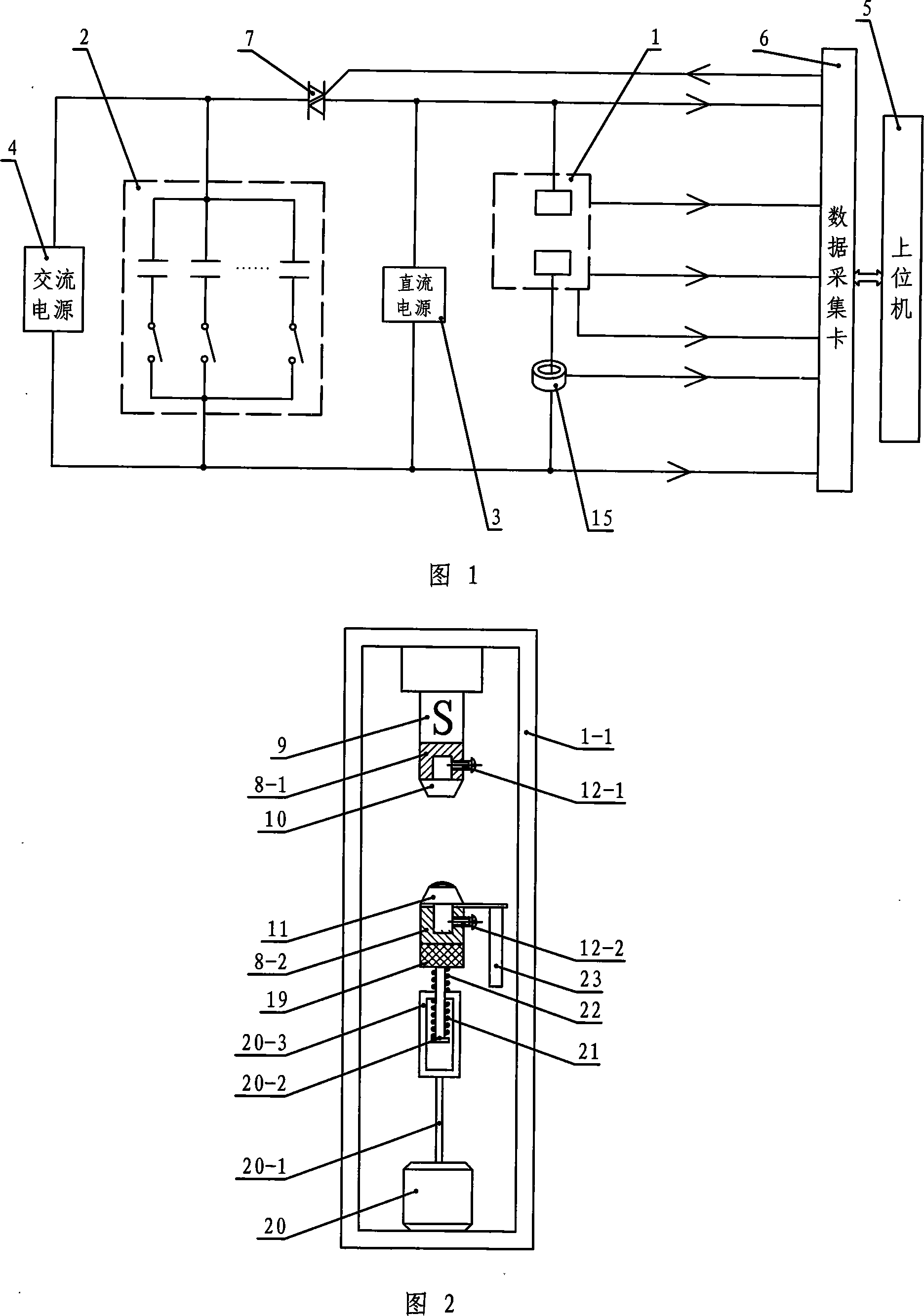
[0007] Specific embodiment 1: Referring to Fig. 1 and Fig. 2, this embodiment consists of an electric contact mechanical movement operation test device 1, a low-voltage constant current power supply 3, an AC power supply 4, a host computer 5 and a thyristor switch 7, which can be controlled The anode of the silicon switch 7 is connected to the first power supply terminal of the AC power supply 4, the cathode of the silicon controlled switch 7 is connected to the first power supply terminal of the electrical contact mechanical movement operation test device 1, and the second power supply terminal of the AC power supply 4 is connected to the electric contactor. The second power supply end of the contact mechanical movement operation test device 1 is connected, the control signal input end of the thyristor switch 7 is connected with the control signal output end of the data acquisition card 6, and the positive end of the low voltage constant current power supply 3 is connected with...

specific Embodiment approach 2

[0009] Specific embodiment 2: Referring to Fig. 1, this embodiment adds a capacitor bank 2 on the basis of specific embodiment 1, the first power supply end of the capacitor bank 2 is connected to the anode of the thyristor switch 7, and the second terminal of the capacitor bank 2 The power terminal is connected to the second power terminal of the electrical contact mechanical movement operation testing device 1 . When the AC power supply 4 adopts an ordinary AC system, it has the advantages of simplicity and directness, good waveform conditions of the power supply, and convenient voltage adjustment; the disadvantage is that the electrical capacity of the laboratory under general conditions is limited, and its experimental current level is mostly less than 100A. , and frequent on and off operations will cause serious interference to other electrical equipment in the circuit, especially electronic instruments and computer equipment, affect their service life, measurement accurac...

specific Embodiment approach 3

[0010] Specific embodiment three: Referring to Fig. 2, the difference between this embodiment and specific embodiment one or two is that the electrical contact mechanical movement operation test device 1 includes a static contact base 8-1, a moving contact base 8-2, Force measuring device 9, static contact 10, moving contact 11, electromagnetic exciter 20, ejector rod 20-1, inverted T-shaped transmission rod 20-2, rectangular frame 20-3, displacement measuring sensor 23, force measuring device 9 is arranged on the upper end surface of the inner side wall of the outer casing 1-1 of the electrical contact mechanical movement operation test device, and the welding force signal output end of the force measuring device 9 is connected with the welding force signal input end of the data acquisition card 6, statically The contact base 8-1 is set on the lower end surface of the force measuring device 9, the static contact 10 is set on the static contact base 8-1, the power end of the st...


PUM


Abstract

A device for testing the electrical erosiveness of the electrical contact material is provided, which relates to a test equipment for research on the electrical erosiveness of the electrical contact material. The invention comprises an electrical source, an electrical load, a control circuit, an executive body for operation of the electrical contact and the control and measuring system of the arc process. The test equipment can conveniently adjust the electric parameters of the test circuit and the correct operating parameters of the examined electrical contact, which solves the problems in the existing testing device that the current device for testing the electrical erosiveness of the electrical contact material can not detect and control the correct displacement of the electrical contact and can not realize the synchro control to the relationship between the making and breaking operation and the power phase by the electrical contact. Through the accuracy control to the correct displacement process of the electrical contact in the testing process as well as the strict restriction to the phase angle condition corresponding to the making and breaking process of the electrical contact, the device avoids the discreteness of the testing result of the electrical erosiveness of the electrical contact material, which provides equipment means and experimental basis for the research on the mechanism of the electrical erosiveness of the electrical contact material.

Description

technical field [0001] The invention relates to a test device for studying the electric erosion performance of electric contact materials, which belongs to the field of electromechanical integration equipment. Background technique [0002] Although semiconductor devices are being used more and more widely in the field of electrical industry, contact appliances still occupy a dominant position in the field of power transformation and distribution. Compared with semiconductor devices, contact appliances have the characteristics of low price, small contact resistance, good insulation performance, strong anti-overload ability, intuitive and reliable action, and good anti-interference performance. However, due to the electrical erosion of the electrical contact material of the contact electrical appliance by the arc process accompanying the switching and breaking operations, the electrical life of the contact electrical appliance is far from that of the power semiconductor device...

Claims


Application Information

Patent Timeline
IPC IPC(8): G01N33/00
Inventor 邵文柱崔玉胜甄良杨丽
Owner HARBIN INST OF TECH
Why Eureka
Try Eureka