Multi-optical fiber melt-pulling method

A multi-fiber, multi-fiber technology, applied in the coupling of optical waveguides, etc., can solve the problems of fewer taps, small bandwidth, and large signal attenuation, and achieve the effects of less power loss, round shape, and small attenuation

Inactive Publication Date: 2008-06-11
莱特尔科技(深圳)有限公司
View PDF0 Cites 9 Cited by
  • Summary
  • Abstract
  • Description
  • Claims
  • Application Information

AI Technical Summary

Problems solved by technology

[0003] In order to overcome the above-mentioned bottleneck of optical fiber fusion drawing technology, solve the problems of small number of taps that can be supported by optical fiber fusion drawing products, poor quality of optical fiber fusion, power loss, large signal attenuation, and small bandwidth in the process of optical fiber communication transmission

Method used


Image

  • Multi-optical fiber melt-pulling method

Examples


Embodiment Construction

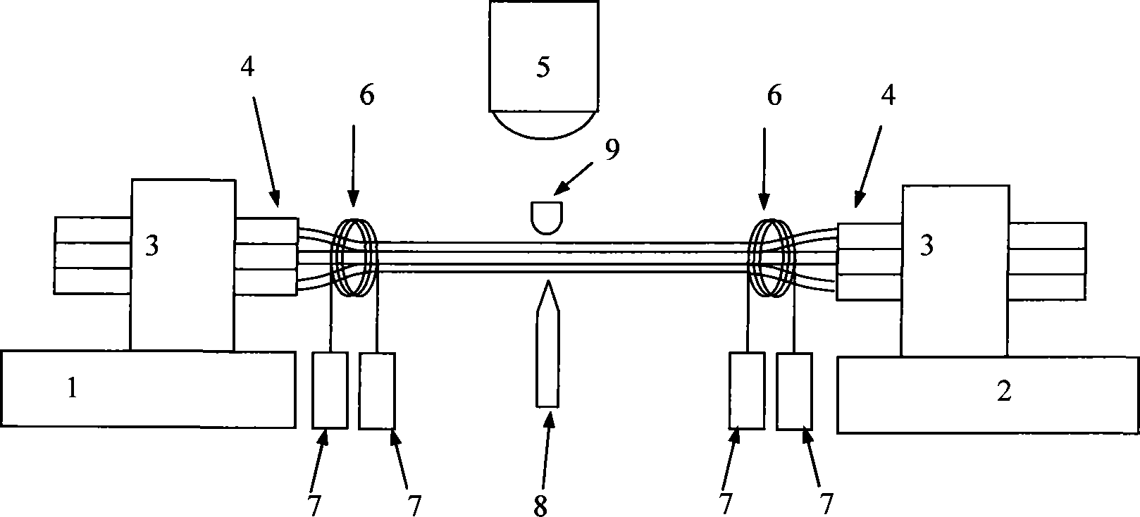
[0015] Referring to the accompanying drawings, the steps of the fiber melting process are as follows:

[0016] A. Adsorb the fiber bundle 4 on the two suction seats 3, and peel off the cladding of the middle section of each optical fiber at an appropriate length to expose the bare fiber. The two suction seats 3 are used to fix the fiber bundle 4 to make it close and straighten ;

[0017] B. Tie two heavy hammers 7 at the two ends of the fiber filament 6, bind them on the bare optical fibers at the left and right ends respectively, and gather the multiple optical fibers of the optical fiber bundle by the gravity of the heavy hammers;

[0018] C. The burner 5 is installed on a platform that can move up and down, front and back, left and right, and moves to the melting and drawing position of the bare optical fiber under the control of the computer. The burning head 5 forms a torch through combustible gas combustion, and forms a high temperature at the melting and drawing positio...


PUM


Abstract

A method for melting and pulling multi-fibre is provided, which can melt and pull a plurality of fibers by binding. The method can also take fine control to melting and pulling by computer, and can solve the problems of the limited taps supported by fibre melting and pulling products, low quality of fibre melting and pulling, lose of power in the process of fibre communication transmission, high attenuation of signals and smaller bandwidth.

Description

technical field [0001] The invention relates to a multi-fiber melting drawing method, in particular to a multi-fiber melting drawing method by bundling and flame melting. Background technique [0002] Optical fiber melting and drawing technology is widely used in the production and application of optical fiber communication equipment such as optical fiber couplers. The current optical fiber melting and drawing technology can handle 2 to 3 fibers during melting and drawing. After processing, the fibers can only be processed in parallel. In phase fusion splicing, the optical fibers cannot be completely refused into a whole. Therefore, the fused optical fiber has power loss, large attenuation, and small bandwidth during the communication transmission process. The number of taps that the optical fiber can support is also small. Contents of the invention [0003] In order to overcome the above-mentioned bottleneck of optical fiber fusion drawing technology, solve the problems o...

Claims


Application Information

Patent Timeline
IPC IPC(8): G02B6/255
Inventor 茅仲明罗喜曾小华于浈浈
Owner 莱特尔科技(深圳)有限公司
Why Eureka
Try Eureka