System for eliminating static

A technology for eliminating static electricity and static eliminators, applied in the direction of static electricity, circuits, electrical components, etc., can solve the problems of increasing energy consumption of CDA, adding rod-shaped static eliminators, increasing costs, etc., to meet the requirements of reducing the size of the installation space, reducing CDA usage, effect of reducing the number of installations

Active Publication Date: 2008-06-11
AU OPTRONICS CORP
View PDF0 Cites 13 Cited by
  • Summary
  • Abstract
  • Description
  • Claims
  • Application Information

AI Technical Summary

Problems solved by technology

However, increasing the number of rod-shaped static eliminators will not only increase the cost, but also affect the configuration and application of the space on the cassette storage area
In addition, the increase in the amount of CDA will not only increase energy consumption, but also cause difficulties in controlling the humidity of the clean room temperature

Method used


Image

  • System for eliminating static
  • System for eliminating static
  • System for eliminating static

Examples


Embodiment Construction

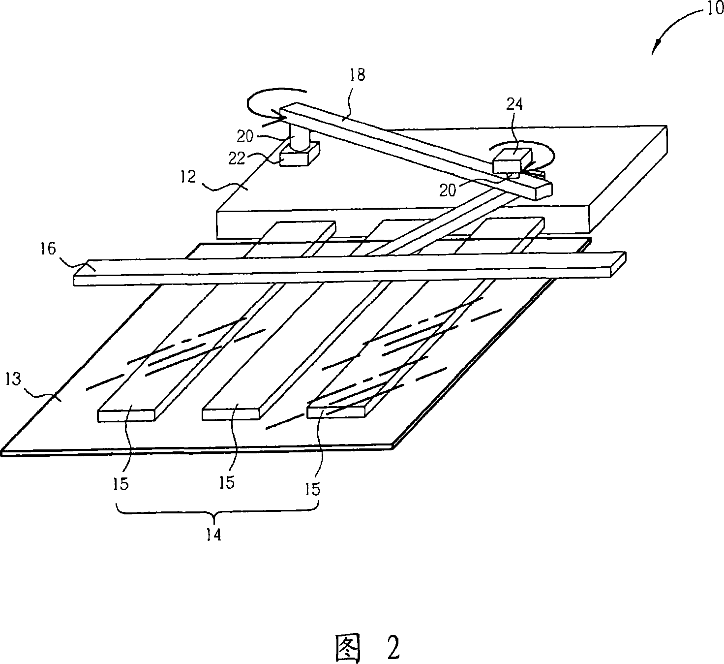
[0041] Fig. 2 is a schematic diagram of a system device for eliminating static electricity proposed by the first preferred embodiment of the present invention. As shown in Figure 2, the static elimination system 10 includes a mechanical arm 12, and the front end of the mechanical arm 12 has a gripper (fork) 14 for picking and placing the glass substrate 13, and the static eliminator 16 is connected by a connecting rod group 18 is erected on the mechanical arm 12. Wherein, the static eliminator 16 used in this preferred embodiment can be various types of static eliminator equipment such as rod type, fan type, high frequency type, and light irradiation type, and the clamping jaw 14 also includes a plurality of supporting arms (arm) 15, used to support the glass substrate 13. The connecting rod group 18 connected to the static eliminator 16 has two pivot points 20, and the connecting rod group 18 is controlled by the first servo motor 22 and the second servo motor 24 on the pivo...


PUM


Abstract

A system for static elimination comprises an electric-manipulator, a grip jaw arranged in the front end of the electric-manipulator, a connecting rod set arranged on the electric-manipulator and a static eliminator arranged on the connecting rod set. The static eliminator can reciprocate in a fixed scope to eliminate static by the connecting rod set.

Description

[0001] This application is a divisional application of the No. 200610080122.1 invention patent application with the filing date of April 28, 2006, entitled "A System for Eliminating Static Electricity". technical field [0002] The present invention relates to a system for eliminating static electricity, especially a system for eliminating static electricity on the surface of a large-sized glass substrate in combination with a static eliminator and a mechanical arm. Background technique [0003] With the trend and demand for light, thin, high-resolution, and low-radiation products, flat-panel displays such as plasma display panels (PDP), liquid crystal display panels (LCD), and organic light-emitting panels (OLED) are increasingly favored by consumers. To obtain good manufacturing quality and yield rate, each manufacturing process is very important. [0004] Taking the manufacturing process of thin-film transistor liquid crystal display (TFT-LCD) as an example, since the sur...

Claims


Application Information

Patent Timeline
Patent Type & Authority Applications(China)
IPC IPC(8): H01L21/677H01L21/00H05F3/04B65G47/90B65G49/06
Inventor 刘家彰陈庆育赵启仲
Owner AU OPTRONICS CORP
Why Eureka
Try Eureka