Self-balancing tractor

An automatic balancing and tractor technology, which is applied in the field of agricultural machinery and tools, can solve the problems of inability to adjust the left and right driving wheels, weak chain drive traction, and inability to pull and transport materials, etc., and achieve the effect of wide application range, large load capacity and reliable performance

Inactive Publication Date: 2008-06-18
柴俊兵
View PDF0 Cites 2 Cited by
  • Summary
  • Abstract
  • Description
  • Claims
  • Application Information

AI Technical Summary

Problems solved by technology

[0002] Current tractors generally have two wheels or four wheels. No matter what kind of tractor, the left and right driving wheels are fixed on the same axis, and the left and right driving wheels cannot change with the gradient of the driving area, and the left and right driving wheels cannot be adjusted. There is a phenomenon of tilting and overturning, so it is only suitable for operation on flat ground or areas with small slopes
In addition, the existing mountain tractors use a rocker arm to adjust the height difference. There is no bridge and no load capacity. The traction force of the chain drive is weak. It can only be used for farmland cultivation and harvesting, and cannot pull materials.

Method used


Image

  • Self-balancing tractor
  • Self-balancing tractor
  • Self-balancing tractor

Examples


Embodiment 1

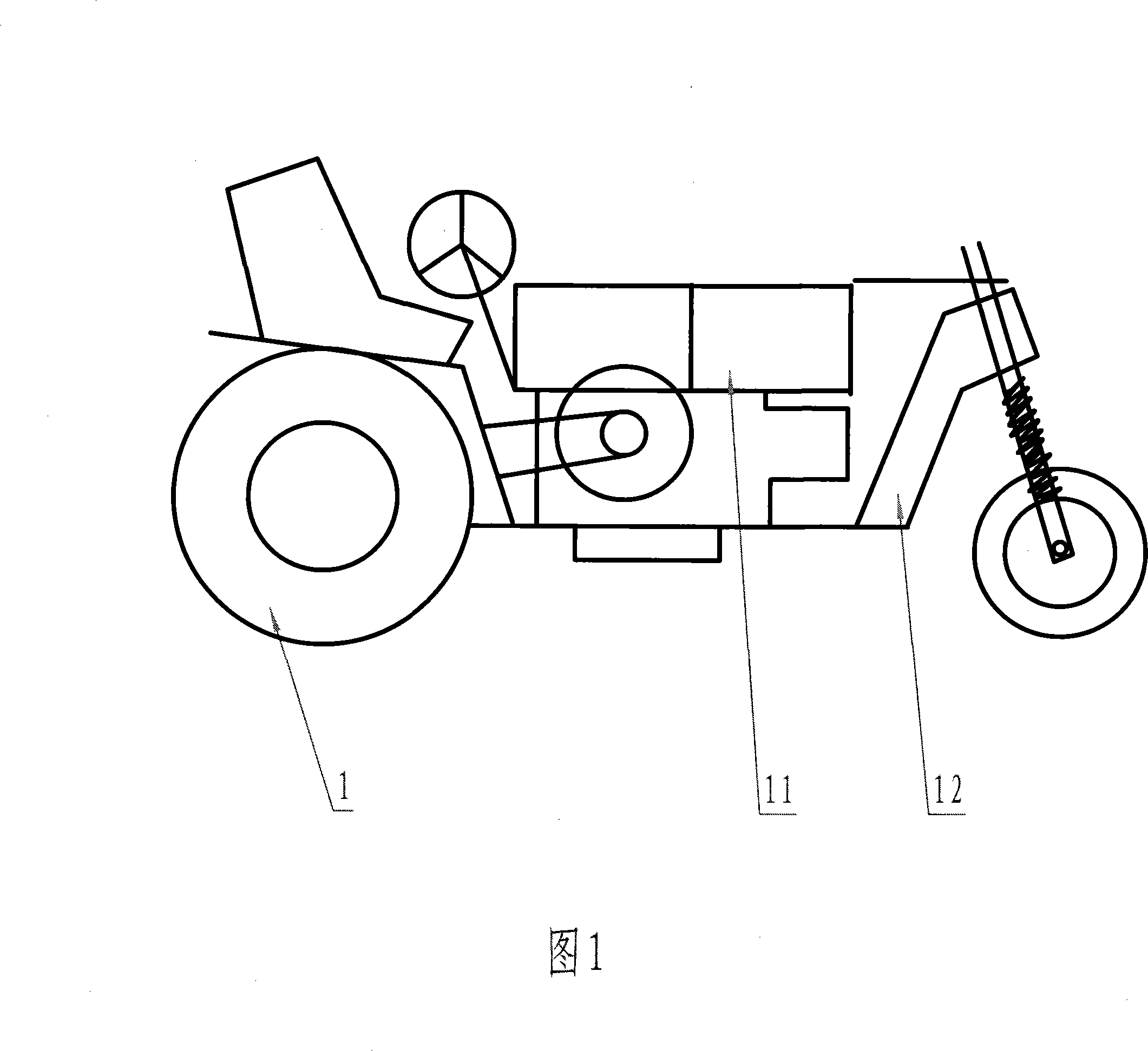
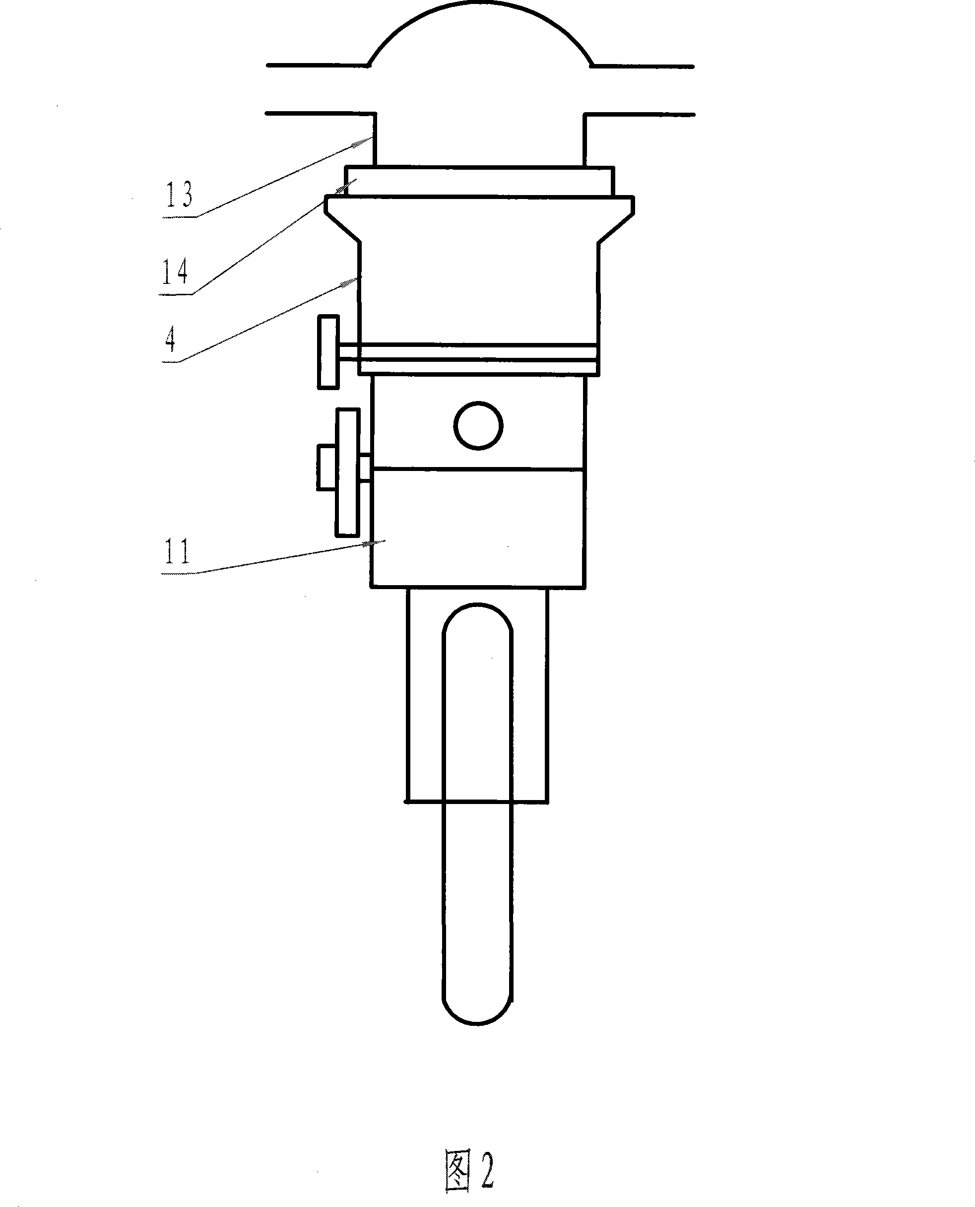
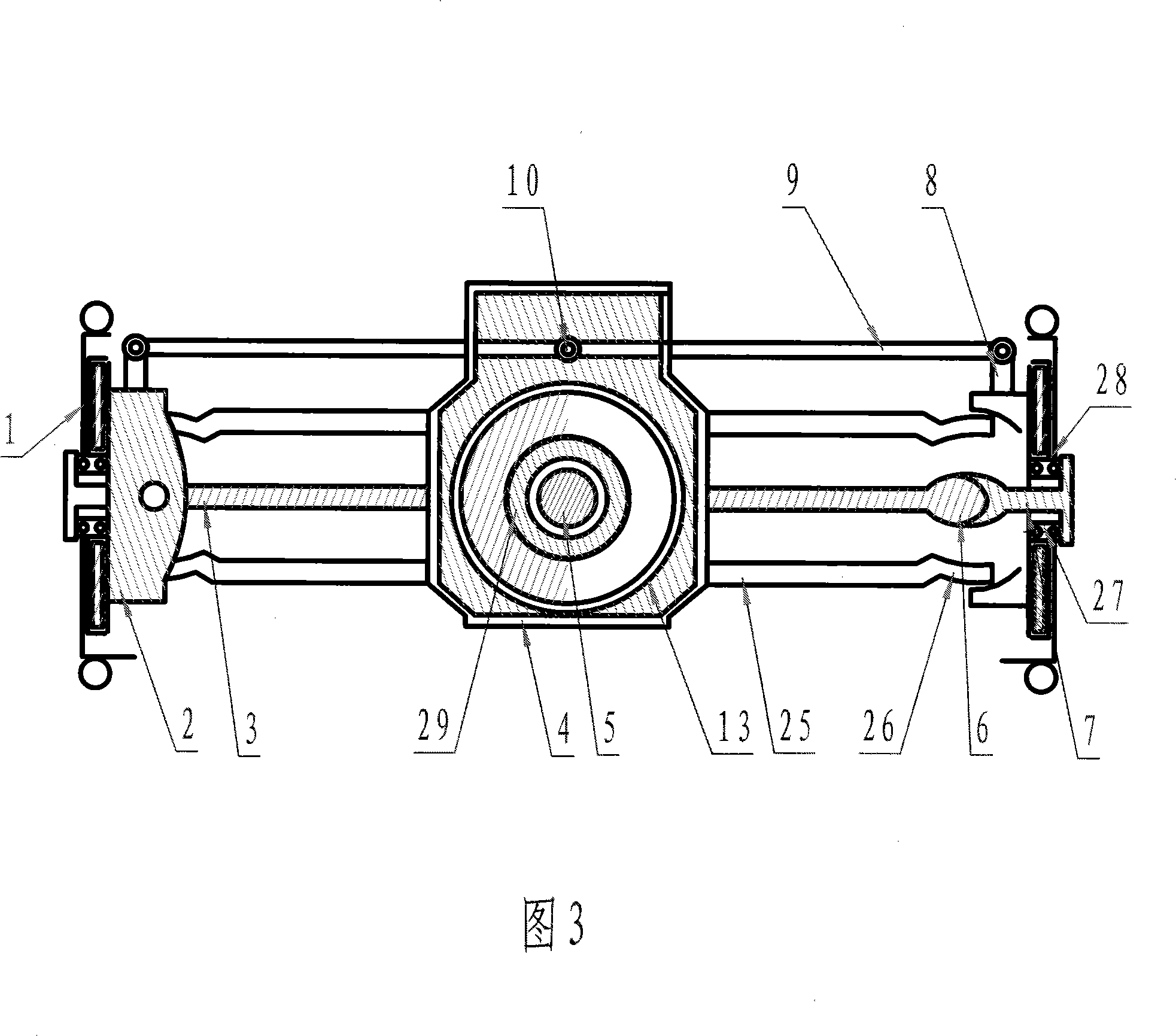
[0015] The front wheel steering assembly seat 12 of the present invention is fixed on the frame of the engine 11, and the frame of the engine 11 is fixed on the gearbox 4, and the final reducer housing 13 is connected with the gearbox 4 by the pressure ring 14 with bolts, and the final reducer The shell 13 is integrated with the spherical support seat 26 through the inner half shaft tube 25, and the left and right spherical support seats 26 are connected with the left and right steering knuckle shells 2 through the kingpin perforation, and the left and right steering knuckle shells 2 are integrated with the left and right steering knuckle journals 27. The moving plate is fixed to the left and right knuckle shells 2, the left and right knuckle journals 27 are connected to the left and right hubs 28 through bearings, the left and right hubs 28 are fixed to the left and right drive wheels 1, the left and right knuckle shells 2 are fixed to the left and right knuckle arms 8, and the...

Embodiment 2

[0017] When the utility model is used in hydraulic transmission, a hydraulic oil cylinder is installed between the main reducer housing 13 and the gearbox 4, and the upper and lower ends of the hydraulic oil cylinder are equipped with hydraulic pull arms, and the upper and lower ends of the hydraulic pull arms are connected with the main drive respectively. The reducer housing 13 is fixed to the gearbox 4, the output of the hydraulic pump passes through the hydraulic valve handle, and the hydraulic valve handle is activated to make the hydraulic oil cylinder rise and fall, and the main reducer housing 13 drives the drive wheel to move up and down through the balance drive axle.

Embodiment 3

[0019] When the utility model is used in a walking tractor, the front wheel steering assembly seat (12) is removed, and only the control handle is fixedly connected with the gearbox 4, and the two ends of the main reducer 16 are respectively connected with the jaw-type clutch, and the jaw-type The clutch is connected with the left and right inner half shafts 3 . The left and right steering pulls the clutch through the fork, the clutch is separated, and the left and right steering drives the driving wheel 1 to travel.


PUM


Abstract

The invention relates to a self-balancing tractor belonging to the agricultural machinery field, which is characterized in that the internal half-shaft tubes of the left and right two ends of a main reducer shell of a balance drive axle are respectively connected in sequence with a spherical bearing, a knuckle shell, a brake disc, a neck journal link of knuckle, a neck journal of knuckle and a drive wheel link. The rear end of the central transmission shaft tube on a gearbox is nested with the main reducer shell. The angular wheel on the counter shaft of the gearbox of a transmission mechanism is meshed with an angular wheel of the central transmission shaft. The other end of the central transmission shaft is connected to the main reducer. The gearbox is provided with a high-low difference balance mechanism, a regulating switch and a lead weight link. The motor is respectively meshed with a transmission gear, a worm, a worm gear, the 60 degree gear ring arranged on the joint of a small gear, the gearbox and the main reducer shell. With the invention, the vehicle body can maintain the state of balance and the phenomenon of tilting and overturning are not easy to occur. Thus the driver can be in safe operation. The operation is simple with reliable performance, low costs, large carrying capacity, strong traction and a wide range of use.

Description

1. Technical field: [0001] The invention relates to an automatic balancing tractor, which belongs to the field of agricultural machinery. 2. Background technology: [0002] Current tractors generally have two wheels or four wheels. No matter what kind of tractor, the left and right driving wheels are fixed on the same axis, and the left and right driving wheels cannot change with the gradient of the driving area, and the left and right driving wheels cannot be adjusted. If there is a phenomenon of tilting and overturning, it is only suitable for operation on flat ground or areas with small slopes. And the existing mountain tractor adopts the rocker arm type to adjust the height difference, has no bridge and has no load capacity, and the chain drive traction force is weak, so it can only be used for farmland cultivation and harvesting, but cannot pull and transport materials. 3. Contents of the invention: [0003] The object of the present invention is to provide a tractor...

Claims


Application Information

Patent Timeline
Patent Type & Authority Applications(China)
IPC IPC(8): B60K17/28
Inventor 柴埃仓柴俊兵
Owner 柴俊兵
Why Eureka
Try Eureka