Single end LED energy-saving lamp and drive circuit thereof

A technology of LED energy-saving lamps and LED light sources, applied in the direction of lamp circuit layout, circuits, energy-saving control technology, etc., to achieve the effects of small irradiation area, increased heat dissipation area, and high light efficiency

Inactive Publication Date: 2010-07-28
DONGGUAN PERFECT SCI & TECH
View PDF2 Cites 0 Cited by
  • Summary
  • Abstract
  • Description
  • Claims
  • Application Information

AI Technical Summary

Problems solved by technology

The high-power LED drive circuits in the prior art all adopt the constant voltage drive mode. The disadvantage of this mode is that the brightness of the LED will be inconsistent with the change of the current of the circuit. The damage will increase the overall current, which will easily lead to damage and shorten the life of the entire LED group. Therefore, this driving circuit needs to be improved urgently.

Method used


Image

  • Single end LED energy-saving lamp and drive circuit thereof
  • Single end LED energy-saving lamp and drive circuit thereof
  • Single end LED energy-saving lamp and drive circuit thereof

Examples


Embodiment 1

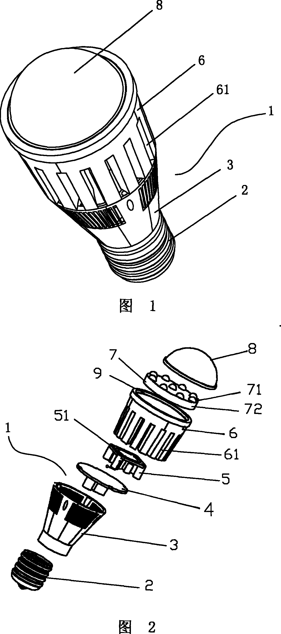
[0031] Embodiment 1: see Figure 1 ~ Figure 2 , a single-ended replacement LED energy-saving lamp 1 provided by the present invention, which includes a plurality of LED light sources, which is a cylindrical shape as a whole, and also includes a metal joint 2, a lamp holder 3, a Drive circuit board 4, a fan 5, a heat sink 6, an LED light board 7, a lens 8; the lamp holder 3 and the heat sink 6 are cylindrical metal components, and the metal joint 2 is arranged on the lamp holder 3, the drive circuit board 4 is provided with a drive circuit, which is set in the lamp holder 3, the fan 5 and LED light board 7 are set in the heat sink 6, and the lens 8 is set in the The front part of the heat sink 6; the electrodes of the metal joint 2, the drive circuit board 4, the fan 5 and the LED light board 7 are electrically connected to each other; it also includes a reflective lamp cup 9, which is an opening forward, and the inner wall is a reflective surface The trumpet-shaped member is ...

Embodiment 2

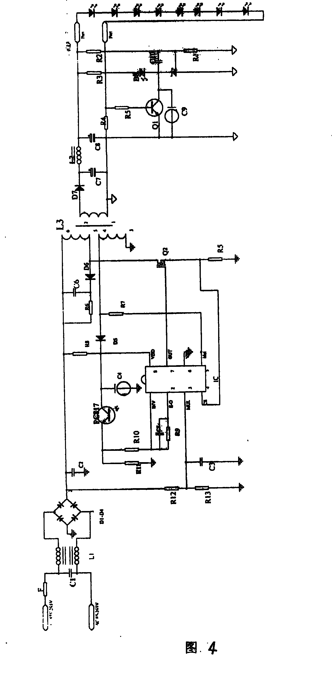
[0038] Example 2: see Figure 4 , Figure 5 , a kind of single-ended replacement LED energy-saving lamp and its drive circuit provided by the present invention, its basic structure is the same as that of Embodiment 1, the difference is that the metal used in the single-ended replacement LED energy-saving lamp 1 Connector 2 is a square connector used in conjunction with the PLC tube G24 interface, which includes a plug body 21 and two metal electrodes 22 arranged on the body 21, which can be directly plugged into the G24 interface; The lens 8 is a concave lens with an astigmatism effect, specifically a double-sided concave lens.

[0039] In other embodiments, the metal joint 2 can also be a variety of joints that are used with other lamp sockets such as E14, E40, etc.; the lens 8 can also be a flat mirror or other types Convex lens, concave lens.


PUM


Abstract

The invention discloses a single-end replacing LED energy saving lamp which comprises a plurality of LED optical sources. The whole invention is in a column shape. The invention also comprises a metal joint, a lamp holder, a drive circuit, a fan, a radiating seat, an LED optical plate and a lens that are connected in turn from the back to the front. The lamp holder and the radiating seat are all cylindrical components. The metal joint is arranged in the tail part of the lamp holder. The drive circuit is arranged in the lamp holder. The fan and the LED optical plate are arranged in the radiating seat. The lens is arranged at the front part of the radiating seat. An electrode, a drive circuit board, a fan of the metal joint are electrically connected with the LED optical plate. The invention also discloses a drive circuit used on the lamp. The drive circuit comprises an AC / DC power module. The module comprises a rectification circuit, an isolation voltage variable circuit and a constantcurrent circuit that are connected in series in turn. A commercial power AC power supply is connected with the input end of the rectification circuit. The output end of the constant current circuit is connected with the LED optical plate.

Description

technical field [0001] The invention relates to an LED lamp, in particular to a single-ended LED energy-saving lamp and a drive circuit thereof which are equipped with a constant current drive circuit and can directly replace existing incandescent bulbs or fluorescent lamps. Background technique [0002] Lamps in the prior art, incandescent lamps are the first generation of lighting fixtures, which adopt the principle of metal wire energization and light emission. Extensive; fluorescent lamps in the prior art belong to gas discharge lamps, also known as hot-cathode low-pressure mercury fluorescent lamps, which have gradually replaced incandescent lamps and become the second-generation mainstream lighting source. , but its power consumption is still relatively large; a small part of it continues to use the lamp holders of the original incandescent lamps and other lamps, and most of them have developed special lamp holders. With the development of solid-state lighting techno...

Claims


Application Information

Patent Timeline
Patent Type & Authority Patents(China)
IPC IPC(8): F21V17/00F21Y101/02H01L23/36F21V29/02F21V5/04H05B37/02F21V29/503F21V29/60F21Y115/10
CPCF21Y2101/02F21V3/00F21K9/13Y02B20/40F21K9/135F21V29/2275F21V29/02H01L2924/0002F21V29/80F21V29/67F21K9/23F21K9/232F21Y2115/10H01L2924/00F21V29/89F21V29/74
Inventor 安波
Owner DONGGUAN PERFECT SCI & TECH
Why Eureka
Try Eureka